Endless boot fixing band and manufacturing method thereof

a technology of fixing band and end-of-boot, which is applied in the direction of hose connection, coupling, transportation and packaging, etc., can solve the problems of grease leakage, coupling portion breakage, band needs more space in its width, and bulky band, so as to prevent grease leakage out of the boot, excellent corrosion resistance, and manufactured simple

Inactive Publication Date: 2010-02-09
NHK SPRING CO LTD
View PDF15 Cites 3 Cited by
  • Summary
  • Abstract
  • Description
  • Claims
  • Application Information

AI Technical Summary

Benefits of technology

[0008]The above-mentioned endless, ring-like boot-band has a uniform cross-sectional shape throughout its circumferential direction, and therefore the surface pressure generated on the boot by the inner surface of the boot-band at the time of fastening is constant throughout the circumference of the boot. However, if the surface pressure is constant in this way, the boot and the boot-band easily move relative to each other in a dynamic environment wherein vibrations, inertia moments, shocks, and the like are experienced, and as a result the boot and the boot-band rotate relative to each other. Such rotation causes friction between the boot and the boot-band, and this friction causes abrasion of the boot, which is weaker in strength than the boot-band. Abrasion of the boot causes the boot to become smaller, resulting in reduction of the boot-band's fastening force, and therefore the boot-band cannot sufficiently fasten the boot. Such reduction of the fastening force causes a problem of grease leaking out from the boot.

Problems solved by technology

If those two forces, while acting on the coupling portion, where the aforementioned projection and indentation are fitted together, become too large, sufficient fastening force cannot be secured at the coupling portion, resulting in problems such as leakage of grease and breakage of the coupling portion.
However, if the thickness is increased the boot-band becomes bulky and needs more space in its height direction, and if the width is increased the boot-band needs more space in its width direction.
This creates such a problem that a constant-velocity joint or the like cannot be used in a small space.

Method used


Image

  • Endless boot fixing band and manufacturing method thereof
  • Endless boot fixing band and manufacturing method thereof
  • Endless boot fixing band and manufacturing method thereof

Examples


Embodiment Construction

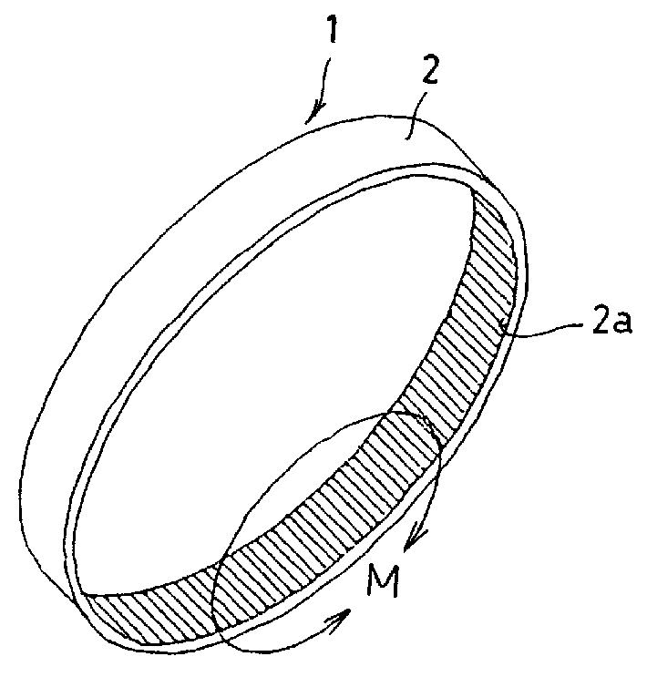
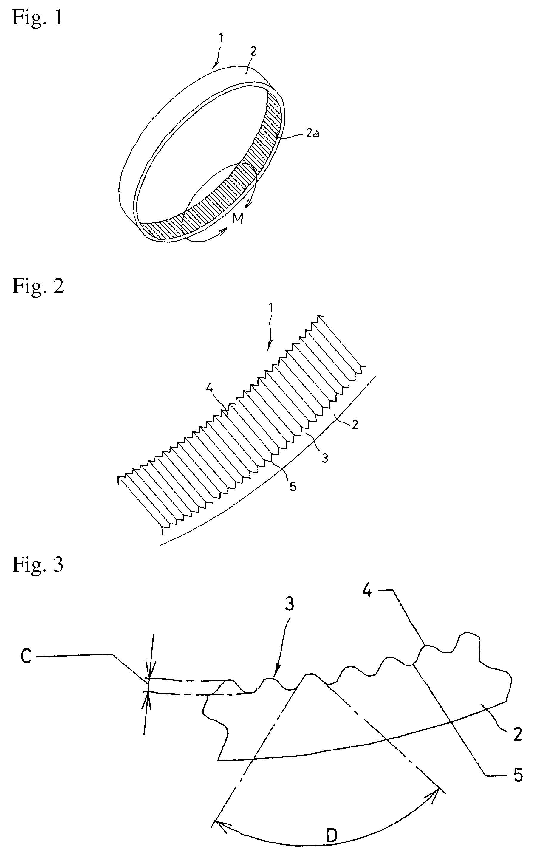
[0046]FIG. 1 is a perspective view of an endless boot-fixing band 1 in one embodiment of the present invention, and FIG. 2 is an enlarged perspective view of the portion M of FIG. 1.

[0047]The endless boot-fixing band (hereinafter referred to as “boot-fixing band”) 1 comprises a band body 2, and combined projections and indentations 3 that are formed as a surface-pressure-altering part on the inner face of the band body 2. The boot-fixing band 1 is used for fastening a boot (not shown), which is made of rubber or resin and that is used for a constant-velocity joint (not shown) of an automobile, onto a tubular member of the constant-velocity joint.

[0048]The band body 2 is formed into an endless ring (annular shape) whose inside diameter is slightly larger than the outside diameter of the boot to be fastened. To fasten the boot, the boot is inserted inside the band body 2, and under this condition the band body 2 is plastically deformed by a special clamping machine so as to reduce the...


PUM

PropertyMeasurementUnit
thicknessaaaaaaaaaa
thicknessaaaaaaaaaa
angleaaaaaaaaaa

Abstract

The rotation of the band in relation to a boot to be fastened is prevented, so that reduction of the boot-fastening force is prevented, thereby preventing leakage of grease from a boot to be fastened, and so that boot-bands can be manufactured simply. An endless boot-fixing band 1 is formed as an endless ring, and is reduced in diameter by plastic deformation so as to fasten a boot by applying pressure onto said boot's outer surface. The boot band is formed entirely of an Al—Mg—Si alloy, and a surface-pressure-altering part 3, which changes the surface pressure for fastening the boot, is formed on the inner surface of the band.

Description

FIELD OF THE INVENTION[0001]The present invention relates to an endless boot-fixing band that is used for fastening and fixing a boot made of rubber or resin to a constant-velocity joint of an automobile, and to a method of manufacturing said boot-fixing band.DESCRIPTION OF THE RELATED ART[0002]In a constant-velocity joint of an automobile, tubular members opposed to each other are covered by / with a boot made of rubber or resin, so that the tubular members are connected together. The constant-velocity joint is supplied with grease so as to keep the joint lubricious at the time of rotation or steering. A boot-band for fastening the boot to the tubular member is used to prevent the grease from leaking from the boot and to prevent dust and water from entering the boot. The boot-band described in Patent Document 1 is such a boot-band.[0003]The boot-band described in Patent Document 1 has a structure such that a projection is provided at one end of a metallic, band-like member, and an in...

Claims


Application Information

Patent Timeline
Patent Type & Authority Patents(United States)
IPC IPC(8): F16L33/20
CPCF16D3/84Y10T24/1408Y10T24/1406Y10T29/5184Y10T24/1478Y10T24/1457Y10T24/148
Inventor OGINO, TAKASHIHEMMI, YOSHIHIROIKEDA, HIROSHI
Owner NHK SPRING CO LTD
Why Eureka
Try Eureka