Fuel-cell system

a fuel cell and system technology, applied in the field of fuel cell systems, can solve the problems of low power generation ability, inability to perform purging at the optimal time point, accumulation of retained nonreactant gas and/or generated water, etc., to prevent the accumulation of nonreactant gas and prevent repeated purging. unnecessary

Inactive Publication Date: 2010-02-02
HONDA MOTOR CO LTD
View PDF25 Cites 0 Cited by
  • Summary
  • Abstract
  • Description
  • Claims
  • Application Information

AI Technical Summary

Benefits of technology

[0010]A first object of this invention is therefore to provide a fuel-cell system having a fuel battery comprising more than one fuel cell that changes chemical energy of a fuel and oxidant to electric energy, wherein purge is conducted at optimum timing for the operating state of (load on) of the fuel battery so as to prevent accumulation of nonreactant gas and / generated water in the fuel battery and that also prevents repetition of unnecessary purges.
[0011]A second object of this invention is therefore to provide a fuel-cell system having a fuel battery comprising more than one fuel cell that changes chemical energy of a fuel and oxidant to electric energy, which enables fuel supply and discharge or purge of residue at starting of the power generation of the fuel battery, without using an external power source, thereby ensuring to obtain a desired electromotive force.

Problems solved by technology

Retention and / or accumulation of nonreactant gas and / or generated water in a fuel battery lowers the ability to generate power.
When purges are programmed to be conducted at predetermined time intervals (time periods between consecutive purges) as in the prior art, however, purge is not always performed at the optimum time point.
This may result in accumulation of retained nonreactant gas and / or generated water because purge is not carried out when necessary or in repeated unnecessary purges.
On the other hand, the method of conducting purges when the output voltage falls below a predetermined level is also liable to result in repeated unnecessary purges when the fuel battery is connected to a high-load external piece of equipment and the output voltage is stable at a low level.
In addition, generated water produced in the course of operation sometimes collects to cause water clogging of the passages and diffusion membranes.
When such a situation arises, fuel (hydrogen gas) supplied to start power generation of the fuel battery is blocked by the retained gas and / or water and does not reach the fuel cell electrodes, occasionally making it impossible to obtain a desired electromotive force.

Method used


Image

  • Fuel-cell system
  • Fuel-cell system
  • Fuel-cell system

Examples


first embodiment

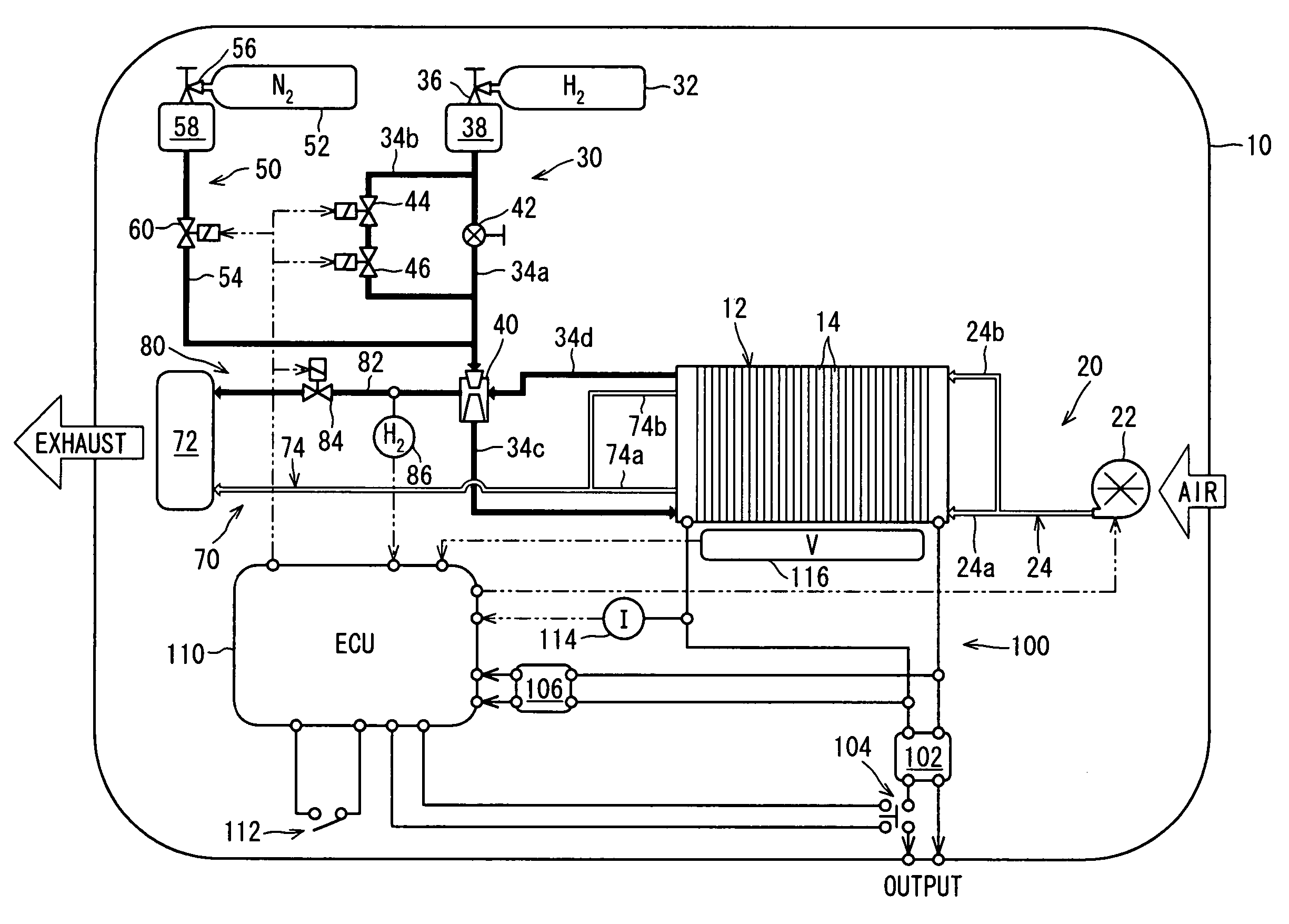
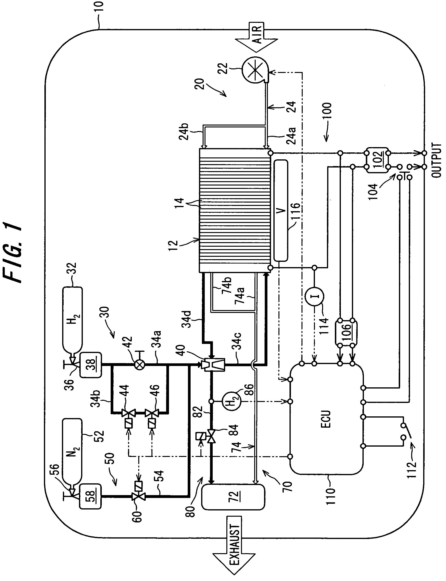
[0025]FIG. 1 is a schematic diagram showing the configuration of a fuel-cell system according to the invention.

[0026]Reference numeral 10 in FIG. 1 designates a fuel-cell system equipped according to the first embodiment. The fuel-cell system 10 is configured as a package of portable size including a fuel battery 12, piping / tubing and other components required for power generation.

[0027]The fuel battery 12 is made up of multiple, typically 70, individual fuel cells (electrochemical cells) 14 installed adjacent to one another and connected in series to have a rated power 1.05 kW. The individual cells 14 are polymer electrolyte fuel cells composed of an electrolytic membrane (solid polymer membrane) that is sandwiched by an air (oxygen) electrode (cathode) and a fuel electrode (anode), and separator plates located outside the respective electrodes. This is a conventional configuration and will not be explained in detail here. Thus, the fuel battery 12 comprises more than one fuel cell...

second embodiment

[0059]A fuel-cell system according to this invention will now be explained with reference to FIGS. 4 and 5.

[0060]FIG. 4 is a view, similar to FIG. 1, but showing the configuration of a fuel-cell system according to the second embodiment of this invention.

[0061]The explanation of the second embodiment will focus on the points of difference from the first embodiment. In the second embodiment, the system configuration is simplified by eliminating the nitrogen gas supply system. The purge gas discharge system 80 has a second purged gas discharge passage (residue discharge passage) 82b that bypasses the forth solenoid valve 84 and a second manual (manually operated) valve 88 is installed in the second purged gas discharge passage 82b.

[0062]The second embodiment aims to achieve the aforesaid second object. Specifically, as discussed above, when the operation of a fuel-cell system is terminated, nitrogen and other nonreactant gases may be retained in the fuel electrode owing to air flowin...

third embodiment

[0075]A fuel-cell system according to this invention will now be explained with reference to FIG. 6.

[0076]FIG. 6 is a view, similar to FIG. 4, but showing the configuration of a fuel-cell system according to the third embodiment of the invention.

[0077]The explanation of the third embodiment will focus on the points of difference from the second embodiment.

[0078]In the fuel-cell system according to the third embodiment, the first manual valve 42 and second manual valve 88 are provided with a coupler 200 that couples the first and second manual valves 42 and 88 for enabling ganged operation of these two valves. More specifically, the coupler 200 couples the first and second manual valves 42 and 48 such that they are opened or closed together. Both the first manual valve 42 and the second manual valve 88 can therefore be simultaneously opened and closed by operating the coupler 200. This enables the supply of hydrogen gas and the discharge of residue to be conducted by a single operati...


PUM

PropertyMeasurementUnit
rated poweraaaaaaaaaa
chemical energyaaaaaaaaaa
currentaaaaaaaaaa

Abstract

A fuel-cell system with a fuel battery comprising more than one fuel cell having a purge gas passage connecting the fuel battery to a purge gas cylinder, a discharge passage connecting the fuel battery to the exterior, solenoid valves each installed in the passages, and an electronic control unit that opens the solenoid valves to open the passages to supply the purge gas to the fuel battery such that residue in the fuel battery is purged to the exterior by the purge gas. The control unit opens the valves at a time interval determined from an output of a current sensor to conduct purge at optimum timing for the battery operating state so as to prevent accumulation of residue in the fuel battery, while preventing repetition of unnecessary purges. Alternatively, manual valves are provided to be manually opened by an operator to open a fuel gas supply passage to supply the fuel gas such that residue is purged by the fuel gas through the discharge passage, thereby enabling fuel supply and purge of residue at starting of power generation, without using an external power source.

Description

BACKGROUND OF THE INVENTION[0001]1. Field of the Invention[0002]This invention relates to a fuel-cell system having a fuel battery comprising more than one fuel cell that changes chemical energy of a fuel and oxidant to electric energy.[0003]2. Description of the Related Art[0004]Retention and / or accumulation of nonreactant gas and / or generated water in a fuel battery lowers the ability to generate power. The practice is therefore to purge the fuel battery of nonreactant gas and / or generated water at regular time intervals, while also monitoring the generated voltage of the fuel battery and carrying out a supplementary purge whenever the generated voltage falls below a predetermined level, as disclosed, for example, in Japanese Laid-open Patent Application No. 2000-243417.[0005]The amount of nonreactant gas and generated water present in a fuel battery varies with the operating state of (load on) the fuel battery. When purges are programmed to be conducted at predetermined time inte...

Claims


Application Information

Patent Timeline
Patent Type & Authority Patents(United States)
IPC IPC(8): H01M2/00H01M8/04
CPCH01M8/04179H01M8/04231H01M8/04388H01M8/04402H01M8/04462H01M8/04559H01M8/04589H01M8/04753H01M8/04761Y02E60/50
Inventor MUTO, GONAKAMURA, HARUOUMENO, HIROSHITODA, SHIGERU
Owner HONDA MOTOR CO LTD
Why Eureka
Try Eureka