
Interlabial pad

a technology of interlabial pads and labiae, which is applied in the field of interlabial pads, can solve the problems of wearer inserting the interlabial pads in the wrong manner, difficulty in detecting the deviation of the interlabial pads by the finger or the labia alone when they are inserted, and difficulty in detecting the deviation of the interlabial pads when inserted, etc., to achieve the effect of suppressing the displacement of the interlabial pads

Inactive Publication Date: 2010-02-02
UNI CHARM CORP
View PDF12 Cites 2 Cited by
  • Summary
  • Abstract
  • Description
  • Claims
  • Application Information

AI Technical Summary

Benefits of technology

[0032]In a ninth aspect of the interlabial pad as described in the first aspect of the present invention, the highly-compressed rigid region includes fiber assembly, and in which the fiber assembly provided in the central region is formed with a higher density than that of the other regions.
[0031]In an eighth aspect of the interlabial pad as described in the first aspect of the present invention, the highly-compressed rigid regions are provided to the central region and to regions along the perimeter extending along the longitudinal direction of the interlabial pad.
[0035]The interlabial pad according to the present invention allows the wearer to fit the highly-compressed rigid region into the recess between the clitoris and the opening of the vagina, into which the interlabial pad is to be inserted, in a manner like that of the wearer fitting a puzzle piece into an appropriate space. This allows the wearer to wear the interlabial pad while confirming whether or not the interlabial pad is at a proper position. Furthermore, the interlabial pad properly fits into the recess, thereby preventing bodily liquid from leaking, and suppressing the displacement of the interlabial pad.

Problems solved by technology

Such an arrangement provides a uniform and linear portion, leading to difficulty in inserting the interlabial pad into the recess of the wearer's body.
However, with such an arrangement, if the pad deviates from the proper location, there is a difficulty in detecting the deviation of the interlabial pad by feel of the finger or the labia alone when it is inserted.
This leads to a situation in which the wearer inserts the interlabial pad in a wrong manner.
In some cases, such a situation results in the leakage of menstrual blood and the displacement of the interlabial pad.
Furthermore, the wearer cannot confirm whether or not the interlabial pad has been inserted in a proper manner until the wearer replaces the interlabial pad.

Method used


Image

  • Interlabial pad
  • Interlabial pad
  • Interlabial pad

Examples


first embodiment

Overall Structure of Interlabial Pad

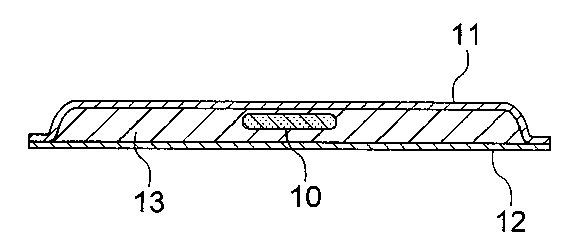
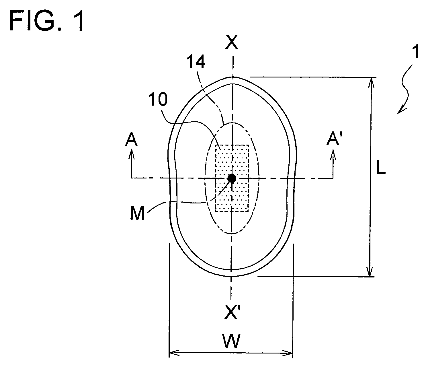
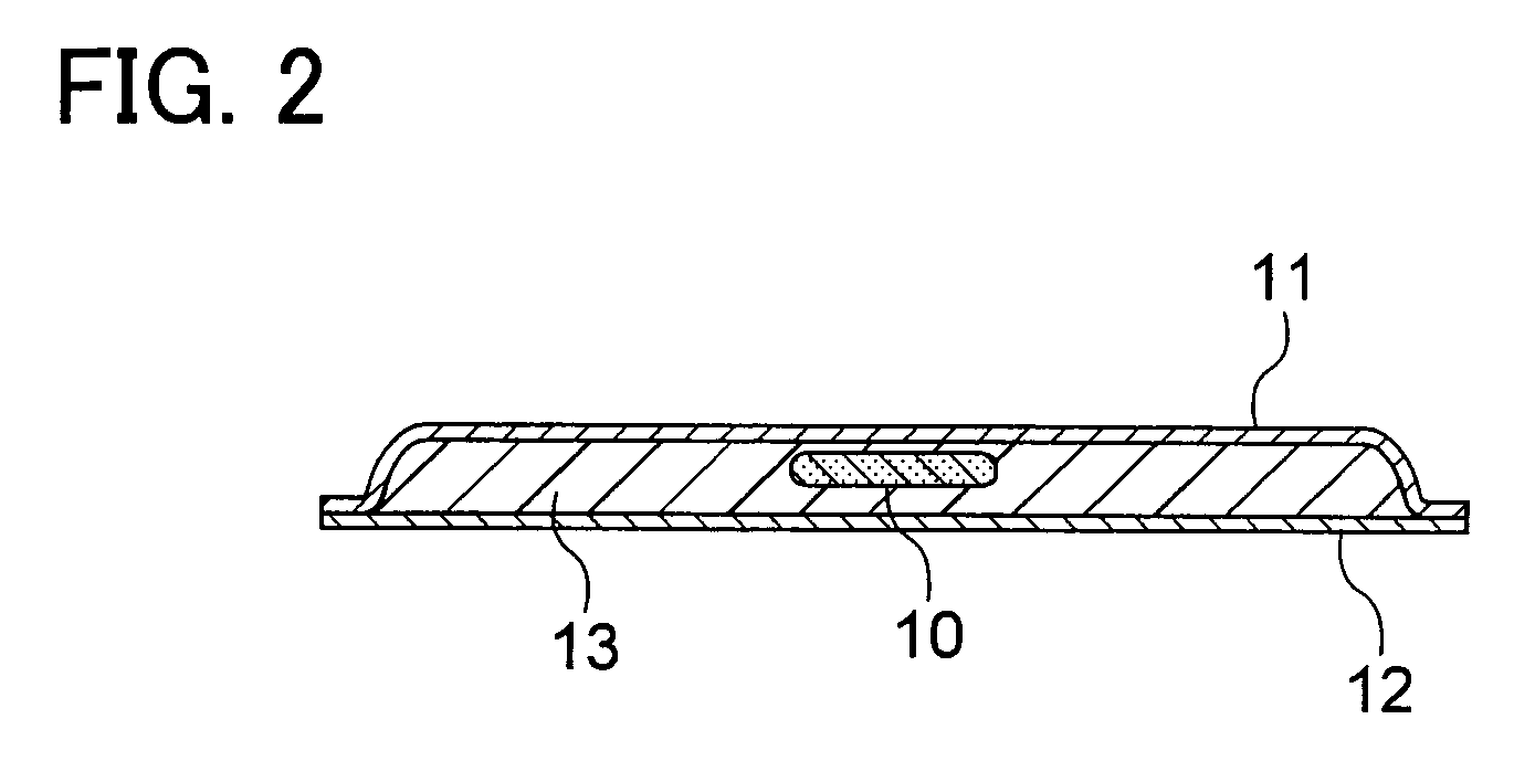
[0085]FIG. 1 is a diagram which shows an interlabial pad according to the present embodiment as viewed from the side which is to be in contact with the wearer's body. FIG. 2 is a cross-sectional view taken along line A-A′ in FIG. 1.

[0086]An interlabial pad 1 according to the present embodiment is formed in an oblong shape as shown in FIG. 1. As shown in FIG. 2, the interlabial pad according to the present embodiment is formed of a liquid-permeable front sheet 11, a liquid-impermeable backing sheet 12, and an absorber 13 introduced between the front sheet 11 and the backing sheet 12. The interlabial pad 1 is worn by the wearer, which is arranged at a wearer's crotch in a front to back direction of the wearer's body. The longitudinal direction of the interlabial pad is corresponding to this front to back direction. In the present specification, “front” means a front of the wearer's body, “back” means a back of the wearer's body. In the present speci...

modification 1

[0098]Next, a description will be given regarding a modification of a structure of the highly-compressed rigid region. FIGS. 15 through 19 are diagrams for describing an interlabial pad according to a Modification 1. FIGS. 20 through 24 are diagrams for describing an interlabial pad according to a Modification 2. Each of such modifications shown in these drawings has a structure in which pulp is provided to a predetermined part so as to form the highly-compressed rigid region, and no pulp is provided to the other part, thereby more effectively improving the functions of the highly-compressed rigid region. Also, FIGS. 25 through 30 are diagrams for describing an interlabial pad according to a Modification 3, having a structure in which the highly-compressed rigid region is formed by adjusting the density of the fiber bundles that form the absorber. FIGS. 31 through 34 are diagrams for describing an interlabial pad according to a Modification 4, having a structure which allows the wea...

modification 2

[0101]An interlabial pad 4 shown in FIG. 20 has a structure in which the highly-compressed rigid region 10 is provided not only to the central region but also to the perimeters extending along the longitudinal direction. That is to say, the highly-compressed rigid region 10 is formed of a central region 10a and perimeter regions 10b. Specifically, the highly-compressed rigid region 10 is provided to three locations approximately along the lateral axis passing through the center of the interlabial pad 4. The modification 1 has generally the same structure as that of the above-described modification 1 having the approximately H-shaped pulp structure, except that pulp is eliminated from a part of the region that extends in the perpendicular direction when it is being worn.

[0102]As shown in FIG. 22, upon folding the interlabial pad 4 according to the Modification 2 with the center line as a reference, the highly-compressed rigid region 10 becomes a structure in which two regions extend ...


PUM


Abstract

An interlabial pad is provided which is capable of being precisely inserted into the recess between the wearer's labia minora, which does not have a linear shape. An interlabial pad 1 includes a highly-compressed rigid region 10, which is highly resistant to being compressed, at a central region along the center line X-X′ in the longitudinal direction. When the interlabial pad is worn, the highly-compressed rigid region 10 protrudes, thereby allowing the wearer to fit the protruding highly-compressed rigid region 10 in the recess between the labia.

Description

[0001]This application is based on and claims the benefit of priority from Japanese Patent Application No. 2005-291768, filed on Oct. 4, 2005, the content of which is incorporated herein by reference.BACKGROUND OF THE INVENTION[0002]1. Field of the Invention[0003]The present invention relates to an interlabial pad having a function of conforming to the shape of the relevant part of the wearer's body when it is being worn, thereby allowing the wearer to properly wear the interlabial pad.[0004]2. Related Art[0005]Examples of conventional feminine hygiene products generally used include sanitary napkins and tampons. Here, a great deal of effort is being put into the development of sanitary napkins which have a function of preventing menstrual blood from leaking from the gap between the sanitary napkin and the wearer's skin, which occurs due to poor adherence of the sanitary napkin to the wearer's skin around the opening of the vagina. On the other hand, the tampons lead to the wearer e...

Claims


Application Information

Patent Timeline
Patent Type & Authority Patents(United States)
IPC IPC(8): A61F13/15A61F13/20
CPCA61F13/47209A61F13/15A61F13/534A61F13/472
Inventor YAMAKI, KOICHITOKUMOTO, MEGUMI
Owner UNI CHARM CORP
Learn More