
System for modulating fuel supply to individual fuel nozzles in a can-annular gas turbine

a canannular gas turbine and fuel supply technology, applied in combustion control, turbine/propulsion engine ignition, lighting and heating apparatus, etc., can solve the problems of unoptimized system, inability to maintain stable combustion in combustor baskets, and unused margins for no/sub>x/sub>optimization, so as to reduce variability, reduce the amount of nox produced, and efficiently manage the fuel flow

Active Publication Date: 2010-02-02
SIEMENS ENERGY INC
View PDF21 Cites 36 Cited by
  • Summary
  • Abstract
  • Description
  • Claims
  • Application Information

AI Technical Summary

Benefits of technology

"This patent describes a fuel modulation system for turbine engines that reduces the production of NOx while maintaining appropriate combustor flame temperatures. The system uses individual inline modulation valves and an overall stage control valve to manage fuel flow to pilot nozzles and combustor baskets. The system calculates peak dynamic pressure levels for each combustor basket and adjusts the fuel flow to maintain the desired flame temperatures. The system also allows for independent adjustment of fuel flow to each combustor basket and reduces NOx production relative to conventional systems while maintaining the same operating conditions."

Problems solved by technology

However, maintaining stable combustion in a combustor basket is very difficult to achieve without having a relatively high temperature region, typically referred to as the pilot region, that produces a relatively high amount of NOx.
Because the individual combustor fuel supply lines are connected to a common fuel manifold, adjusting the system based upon the peak combustor basket with the highest dynamic levels brings the peak combustor back within dynamic limits, however, the system is not optimized as other combustors are operating below the dynamic limits leaving unused margin for NOx optimization in the other combustor baskets.
Thus, a need exists for a more efficient manner of controlling pilot nozzle fuel flow such that dynamic pressures are within an acceptable range and NOx production is limited as much as possible.

Method used


Image

  • System for modulating fuel supply to individual fuel nozzles in a can-annular gas turbine
  • System for modulating fuel supply to individual fuel nozzles in a can-annular gas turbine
  • System for modulating fuel supply to individual fuel nozzles in a can-annular gas turbine

Examples


Embodiment Construction

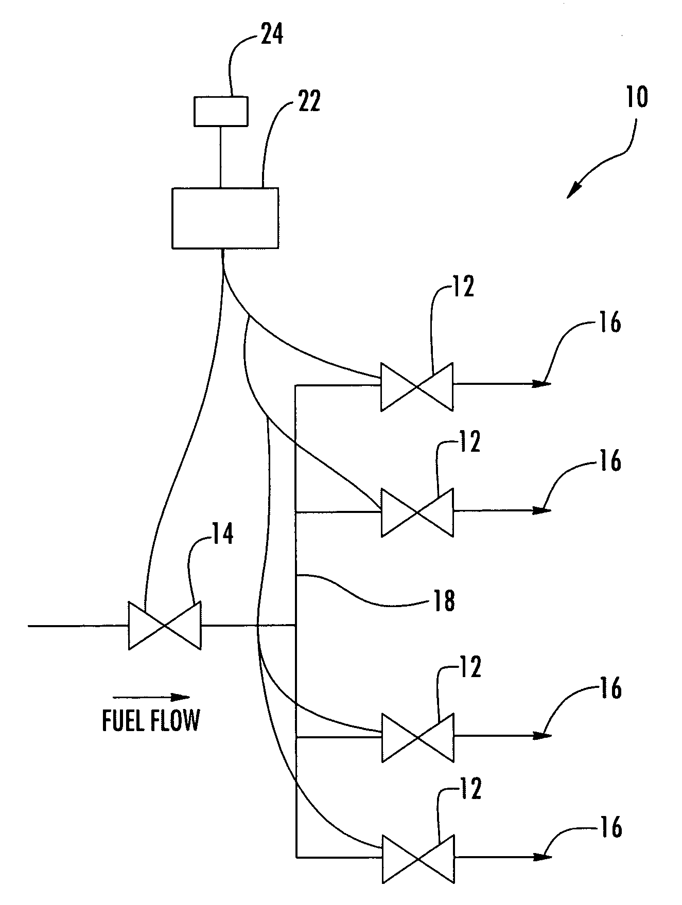
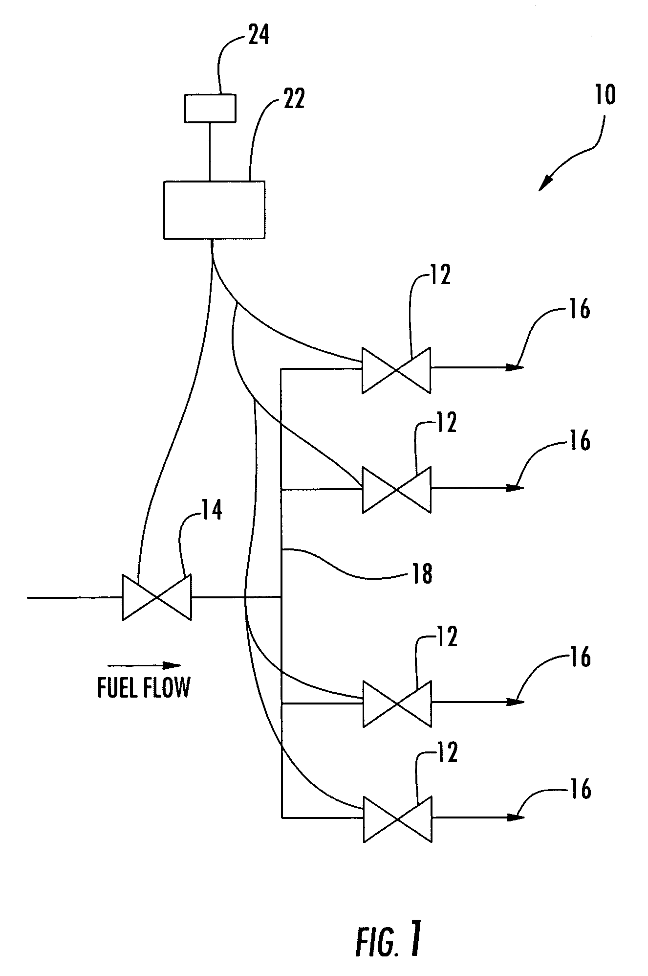
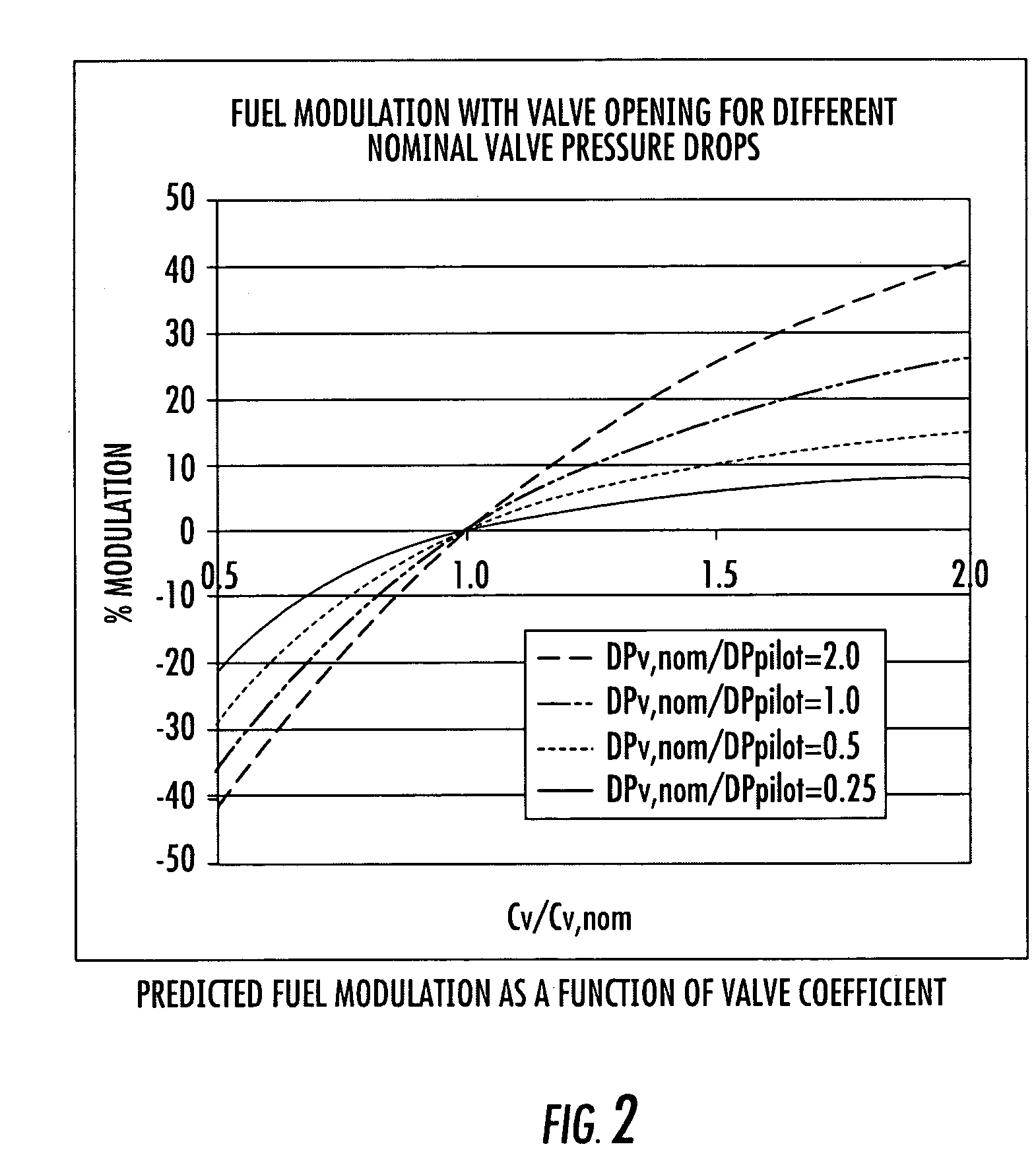
[0015]As shown in FIGS. 1-2, the invention is directed to a fuel modulation system 10. The fuel modulation system 10 may be usable in can-annular combustor systems of turbine engines for more efficiently managing fuel flow to reduce the amount of NOx while maintaining appropriate combustor flame temperatures. The fuel modulation system 10 controls individual inline modulation valves 12 in cooperation with a overall stage control valve 14 to bring a turbine engine through the startup phase and to maintain operating conditions at a load set point while reducing NOx variability between baskets by using individual combustor dynamic pressure measurements.

[0016]The fuel modulation system 10 may include a plurality of inline modulation valves 12 positioned inline in individual pilot fuel feed lines between fuel nozzles 16 and a turbine fuel manifold 18. The turbine fuel manifold 18 may be in fluid communication with the fuel nozzles 16 and the overall stage control valve 14. In addition, t...


PUM


Abstract

A fuel modulation system usable in can-annular combustor systems of turbine engines for more efficiently managing fuel flow to reduce the amount of NOx while maintaining appropriate combustor flame temperatures. The fuel modulation system controls individual inline modulation valves in cooperation with a overall stage control valve to bring a turbine engine through the startup phase and to maintain operating conditions at a load set point while reducing NOx variability between baskets by using individual combustor dynamic pressure measurements. The fuel modulation system may be managed such that individual inline modulation valves remain within a predetermined range of positions relative to a nominal position to reduce NOx variability.

Description

FIELD OF THE INVENTION[0001]This invention is directed generally to fuel supply systems, and more particularly to fuel supply systems for can-annular gas turbine engines.BACKGROUND[0002]In a can-annular gas turbine combustor, differences in air and fuel flow between combustor baskets produce differences in the dynamic pressure and NOx emissions. Typically, dynamic pressure and NOx emissions vary inversely such that as a combustion system is tuned to reduce NOx emissions, dynamic pressure increases. In a traditional dry low NOx (DLN) combustion system, there are four stages: an upstream premixing stage, a non-premixed pilot stage and two main premixing stages. Because the pilot flame burns as a high temperature diffusion flame, the production of NOx and the amount of dynamic pressure in a combustor basket are closely related to the pilot fuel fraction. Ideally, all of the fuel would be premixed prior to being introduced into the combustor basket to reduce NOx production. However, mai...

Claims


Application Information

Patent Timeline
Patent Type & Authority Patents(United States)
IPC IPC(8): F02C9/22F02C9/34
CPCF02C7/26F23N1/002F23N5/16F23R3/343F23R3/46F23N2027/02F23N2037/02F23R2900/00013F23N2227/02F23N2237/02
Inventor RYAN, WILLIAM R.SMITH, ERNEST W.
Owner SIEMENS ENERGY INC
Learn More