Radio communication device, radio communication system and measurement method capable of conducting appropriate transmit power control
a radio communication system and radio communication technology, applied in power management, transmission monitoring, and receiving monitoring, etc., can solve the problems of increasing the cost of the device for implementing ineffective communication quality information measured by sta b>1102/b> so as to enable sta b>1102 to perform the transmission power control, and inability to solve the above-described problems. , to achieve the effect of excellent general versatility
- Summary
- Abstract
- Description
- Claims
- Application Information
AI Technical Summary
Benefits of technology
Problems solved by technology
Method used
Image
Examples
first embodiment
[0130]The first embodiment of the present invention will now be described with reference to FIGS. 1-10. In the first embodiment, description will be made as to how a STA 102 assigned with a communication right controls transmit power when transmitting stream data to a STA 103. In the first embodiment, it is assumed that stream data having its stream identifier TSID (Traffic Stream IDentifier) of “15” is transmitted from STA 102 to STA 103. In the following, stream data having TSID of L (natural number) is expressed as TSIDL.
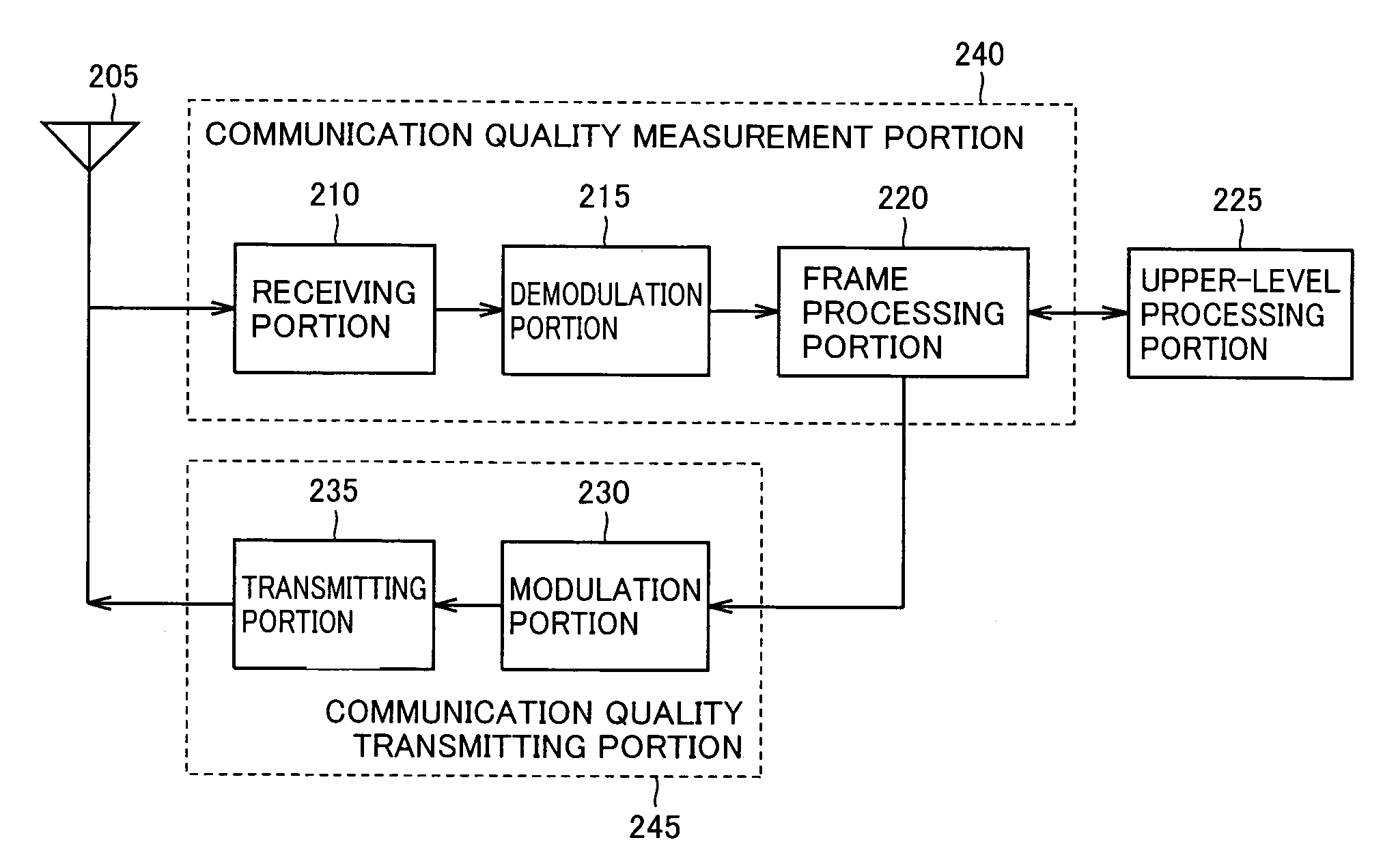
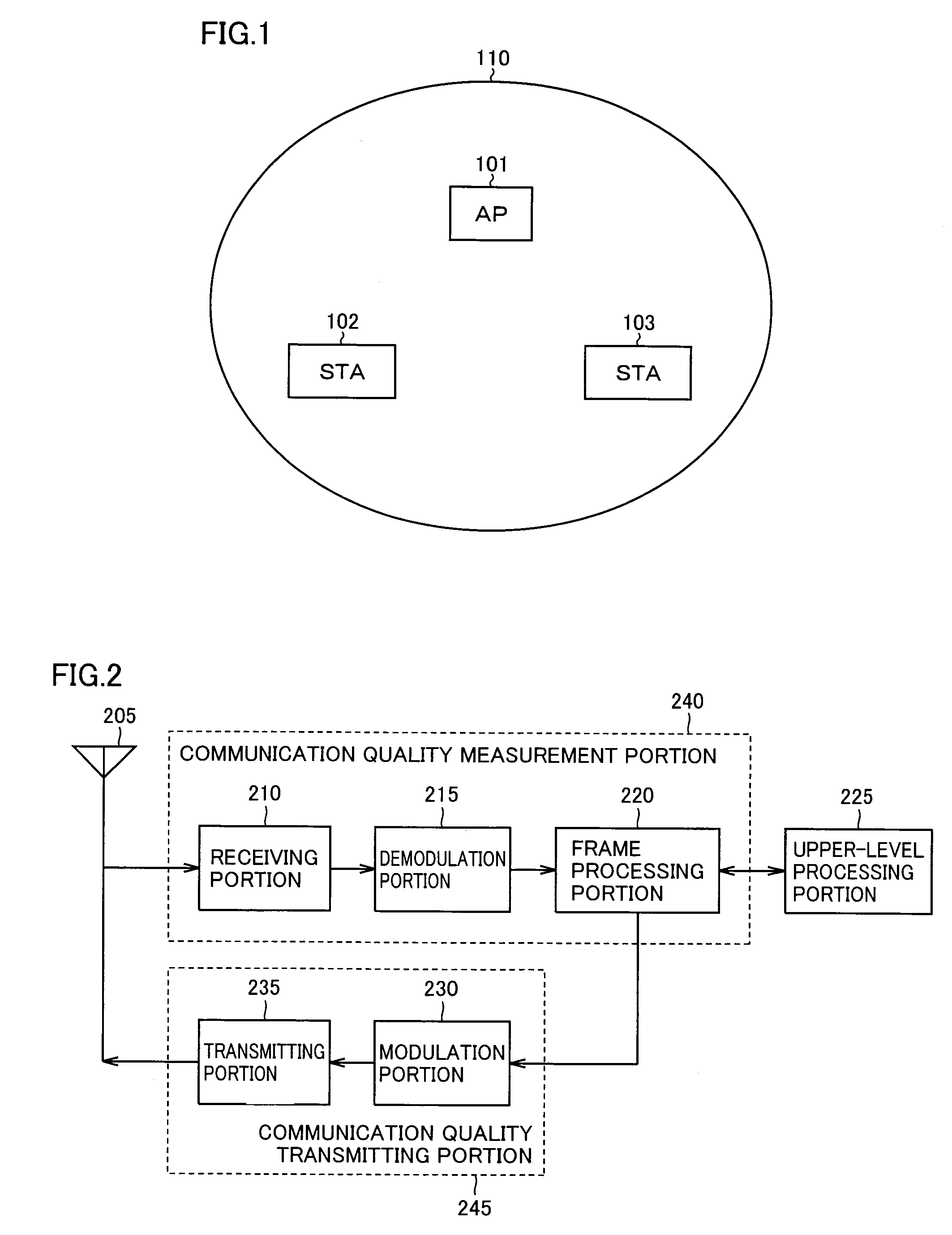
[0131]Firstly, description will be made, with reference to FIGS. 1-4, about the flow where STA 103 serving as a receiving station measures quality of a radio channel (communication quality) for transmitting / receiving frames to / from STA 102, and transmits a frame indicating communication quality information being the measurement result to STA 102.
[0132]FIG. 1 schematically shows an infrastructure network configured with a single BSS (Basic Service Set) 110. An AP ...
first modification
of First Embodiment
[0161]A first modification of the first embodiment will now be described. In the following, differences of the first modification of the first embodiment from the first embodiment will primarily be explained. Explanation was made in the first embodiment about the case where frame processing portion 220 controls transmit power of frames when receiving communication quality information from STA 103 and stores the controlled transmit power as transmit power information in the storage table. In the first modification of the first embodiment, explanation will be made about the case where the time when control of transmit power was carried out (hereinafter, also referred to as “transmit power control time”) is stored in a storage table, and when measurement information including a measurement result of communication quality and information of the time when the measurement was started is received from STA 103, frame processing portion 220 controls the transmit power of t...
second modification
of First Embodiment
[0171]A second modification of the first embodiment will now be described. In the following, differences of the second modification of the first embodiment from the first embodiment and the first modification of the first embodiment will primarily be explained. Explanation was made in the first embodiment about the case where upon receipt of communication quality information from STA 103, frame processing portion 220 controls transmit power of frames, and stores the controlled transmit power in the storage table as transmit power information. Explanation was made in the first modification of the first embodiment about the case where transmit power control time is stored in the storage table and, upon receipt of communication quality information from STA 103, frame processing portion 220 controls transmit power of frames when communication quality measurement start time is later than the transmit power control time.
[0172]In the second modification of the first embo...
PUM
 Abstract
Description
Claims
Application Information
 - R&D
- Intellectual Property
- Life Sciences
- Materials
- Tech Scout
- Unparalleled Data Quality
- Higher Quality Content
- 60% Fewer Hallucinations
Browse by: Latest US Patents, China's latest patents, Technical Efficacy Thesaurus, Application Domain, Technology Topic, Popular Technical Reports.
© 2025 PatSnap. All rights reserved.Legal|Privacy policy|Modern Slavery Act Transparency Statement|Sitemap|About US| Contact US: help@patsnap.com


