
Bit-edge zero forcing equalizer

a zero-forcing equalizer and bit-edge technology, applied in the field of equalization, can solve the problems of warped pulses that are transmitted from a transmitter to a receiver via the communication channel, undesirable interference, and spread of pulses,

Active Publication Date: 2010-01-26
XILINX INC
View PDF21 Cites 9 Cited by
  • Summary
  • Abstract
  • Description
  • Claims
  • Application Information

AI Technical Summary

Benefits of technology

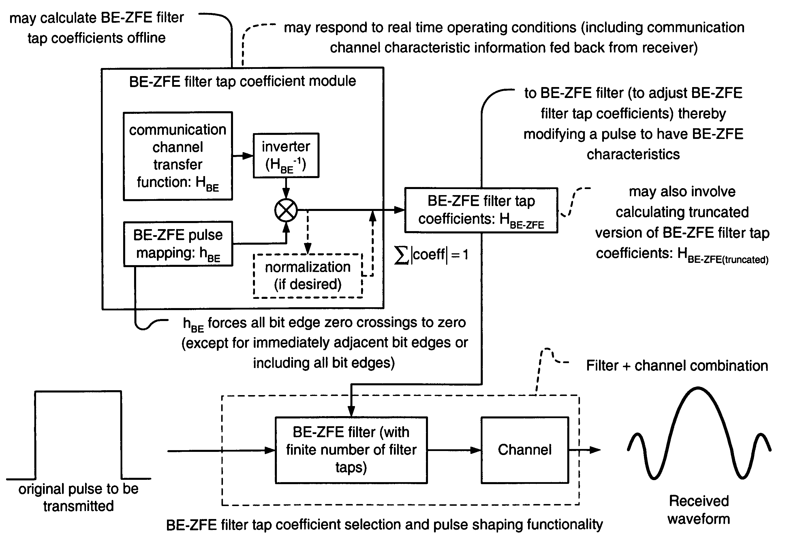
The invention is a method for reducing inter-symbol interference in communication devices. It uses a filter called a BE-ZFE that adjusts the pulse shape sent through a communication channel to minimize inter-symbol interference at the bit edges. The filter tap coefficients are calculated in real-time or offline based on the characteristics of the communication channel. The modified pulse has zero crossings located at the bit edges of each bit period, except those bit edges immediately adjacent to the bit period in which the original pulse is located. The filter tap coefficients can be selected to minimize the absolute values of each filter tap coefficient. The invention can be implemented in various types of communication devices and systems.

Problems solved by technology

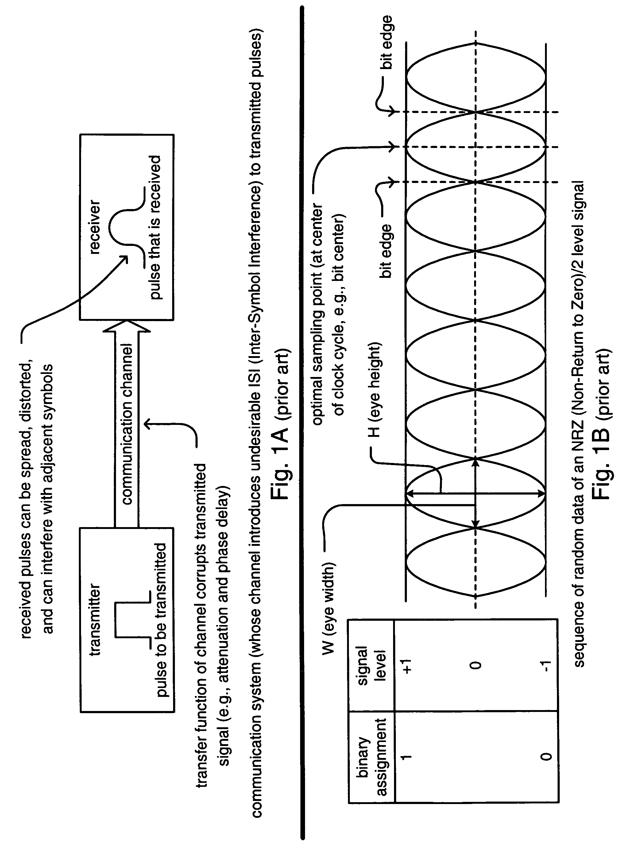
In some communication systems, these pulses may undesirably interfere with one another as they are being transmitted across a communication channel from a transmitter to a receiver.
This communication channel is most oftentimes responsible for causing these deleterious effects.
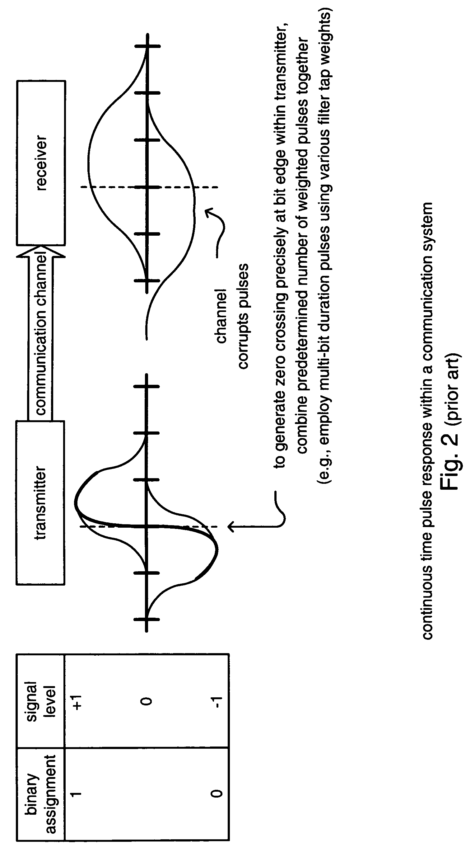
A pulse that is transmitted from a transmitter to a receiver via the communication channel unfortunately is warped, or spread, by the communication channel itself.
Because of this warping, or spreading, of the transmitted pulses from a transmitter to a receiver across the communication channel, pulses that are located in relative close proximity with one another in the sequence of pulses (or sequence of bit periods) may interfere with one another and cause this undesirable ISI.
However, one of the most undesirable deleterious effects of this prior art BC-ZFE approach is that there still can be very significant ISI at the non-bit center locations within the respective bit periods.
While the amplitude noise reduction approach provided by the BC-ZFE may be appropriate for some applications, it does not necessarily fare well for jitter noise limited systems.
For example, a BC-ZFE can leave considerable phase jitter which is inherently a significant problem for phase noise limited communication systems.
This sometimes very large ISI at the other locations within the bit periods besides the bit centers can incur a heavy cost in terms of performance.
For example, this undesirable ISI can be very difficult to deal with when actually implementing a BC-ZFE within a communication device (e.g., in hardware).
A secondary issue is a relatively significant number of filter taps are often required to implement a BC-ZFE effectively.
The combined effect of requiring many filter taps along with the relatively large filter tap coefficient values, thereby requiring devices with larger components therein, can often result in a communication device that does not always meet design operational criterion.
For example, the relatively large size of the communication device can result in significant parasitic loading because of the increased parasitic capacitance of the relatively large device.
Also, because so many filter taps are often required, a relatively high number of high speed delay elements is often required.
These high speed delay elements can require a significant degree of buffering and clock signaling.
These are but some of the many deleterious effects that can be incurred when using a prior art classic BC-ZFE approach to signal shaping.

Method used


Image

  • Bit-edge zero forcing equalizer
  • Bit-edge zero forcing equalizer
  • Bit-edge zero forcing equalizer

Examples


Embodiment Construction

[0052]A novel approach is presented whereby equalization is performed on a signal that contains data (e.g., information bits) to improve the probability of making an accurate decision on data contained within that data signal at a receiver end of a communication channel. This new approach of equalization may be performed using a BE-ZFE (Bit-Edge Zero Forcing Equalizer) as described herein. In a most general description, the BE-ZFE performs equalization by looking at the values of data that occur at the bit edges of a data signal and seeks to drive those associated error terms to zero. This new BE-ZFE approach is a significant departure from the classical prior art BC-ZFE (Bit-Center Zero Forcing Equalizer) approach that looks specifically at the values of the signal at the bit centers and seeks to drive those associated error terms to zero.

[0053]In contradistinction to the prior art BC-ZFE approach, the new BE-ZFE approach looks specifically at the values of the signal at the bit ed...


PUM


Abstract

Bit-Edge Zero Forcing Equalizer. A novel solution is presented by which a BE-ZFE (Bit-Edge Zero Forcing Equalizer) is employed to drive an error term within a data signal to an essentially zero value. This new BE-ZFE looks at values of data that occur at the bit edges of a data signal and drives the associated error term to zero. The new BE-ZFE is appropriately implemented within communication systems that are phase (or jitter) noise limited. Some examples of such communication systems include high-speed serial links one type of which serviced using a SERDES (Serializer / De-serializer) where data that is originally in a parallel format is serialized into a serial data stream and then subsequently de-serialized back into a parallel data stream.

Description

BACKGROUND OF THE INVENTION[0001]1. Technical Field of the Invention[0002]The invention relates generally to communication systems; and, more particularly, it relates to equalization that is performed on signals within such communication systems to assist in making more accurate decisions of data contained therein.[0003]2. Description of Related Art[0004]Data communication systems have been under continual development for many, many years. One very critical factor to assist in making proper decisions within digital communication systems is for a sampling point to have a relatively small amount of ISI (Inter-Symbol Interference). This ISI may be viewed as the deleterious effects resulting from one symbol interfering with those symbols adjacent to or near the symbol of interest within a sequence of symbols.[0005]In a communication system that operates using 2 level signals (e.g. 1 and 0 in digital binary), oftentimes pulses are used to represent the logical 1 and 0 values. These 2 lev...

Claims


Application Information

Patent Timeline
Patent Type & Authority Patents(United States)
IPC IPC(8): H03K5/159H04L25/03
CPCH04L25/03019H04L2025/03624
Inventor BRUNN, BRIAN T.ANDERSON, STEPHEN D.
Owner XILINX INC
Learn More