
Implementation of a strategy for achieving extraordinary levels of surface area and porosity in crystals

a technology of surface area and porosity, applied in the direction of group 3/13 element organic compounds, group 5/15 element organic compounds, mechanical instruments, etc., can solve the problem of not defining the upper limit of surface area for a material, no strategy has yet been outlined, and few systematic approaches exis

Inactive Publication Date: 2010-01-26
MICHIGAN UNIV OF RGT
View PDF58 Cites 64 Cited by
  • Summary
  • Abstract
  • Description
  • Claims
  • Application Information

AI Technical Summary

Benefits of technology

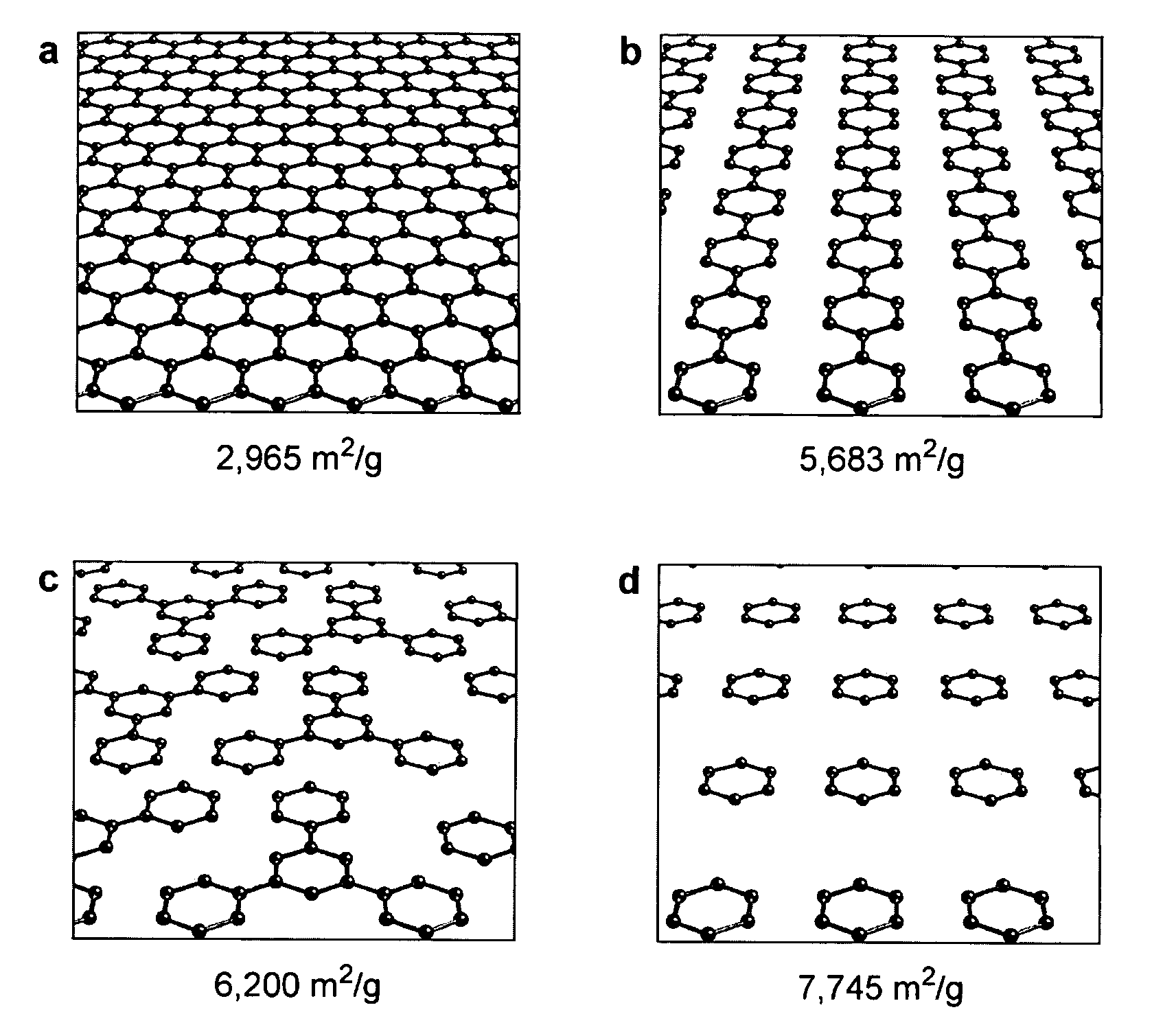
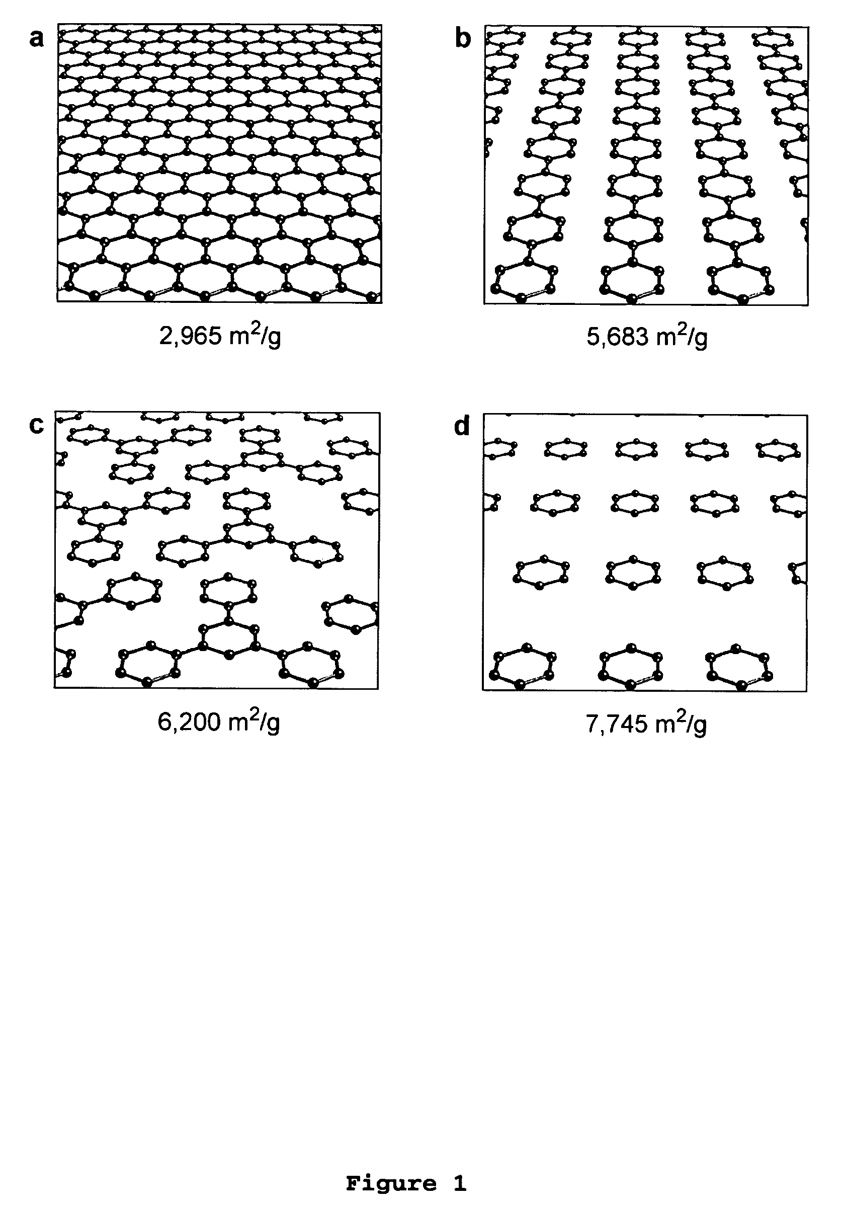
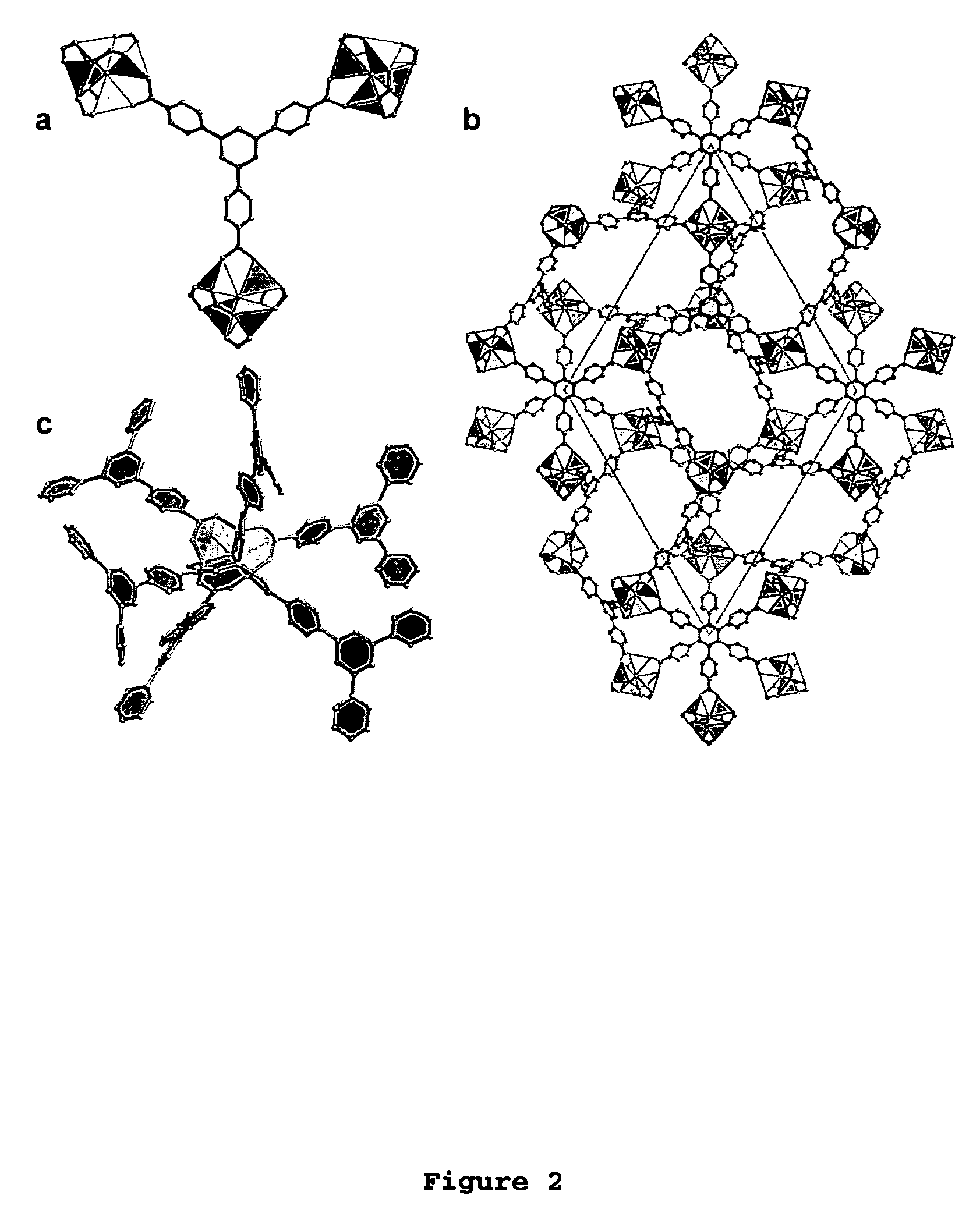
[0011]The present invention provides a general strategy that allows the realization of a structure having, by far, the highest surface area reported to date. In one embodiment of the present invention, a metal-organic framework (“MOF”) comprising a plurality of metal clusters and a plurality of multidentate linking ligands is provided. The methodology of the present invention represents an enhancement of U.S. Pat. Appl. 20

Problems solved by technology

One of the outstanding challenges in the field of porous materials is the design and synthesis of chemical structures with exceptionally high surface areas.
Despite this progress and the critical importance of high surface area to many applications involving catalysis, separation and gas storage, no strategy has yet been outlined to answer the question of what the upper limit in surface area for a material is, and how it might be achieved.
Although desirable, few systematic approaches exist because of the lack of control over molecular assembly and in particular, the inability to control the orientation of atomic groups in crystals.
Although the MOF-5 crystalline structure possesses a number of desirable characteristics, the MOF-5 framework is formed in relatively low yield.
Although such synthesis may produce frameworks with varying pore sizes, attempts to evacuate / exchange guests within the pores often result in the collapse of the host framework making the practical utility of such frameworks limited.

Method used


Image

  • Implementation of a strategy for achieving extraordinary levels of surface area and porosity in crystals
  • Implementation of a strategy for achieving extraordinary levels of surface area and porosity in crystals
  • Implementation of a strategy for achieving extraordinary levels of surface area and porosity in crystals

Examples


Embodiment Construction

)

[0022]Reference will now be made in detail to presently preferred compositions or embodiments and methods of the invention, which constitute the best modes of practicing the invention presently known to the inventors.

[0023]As used herein “linking ligand” means a chemical species (including neutral molecules and ions) that coordinates to two or more metals resulting in an increase in their separation and the definition of void regions or channels in the framework that is produced. Examples include 4,4′-bipyridine (a neutral, multiple N-donor molecule) and benzene-1,4-dicarboxylate (a polycarboxylate anion).

[0024]As used herein “non-linking ligand” means a chemical species that is coordinated to a metal but does not act as a linker. The non-linking ligand may still bridge metals, but this is typically through a single coordinating functionality and therefore does not lead to a large separation. Examples include: water, hydroxide, halides, and coordinating solvents such as alcohols, f...


PUM

PropertyMeasurementUnit
Molar massaaaaaaaaaa

Abstract

The present invention provides a metal-organic framework (“MOF”) comprising a plurality of metal clusters and a plurality of multidentate linking ligands. Each metal of the plurality of metal clusters comprises one or more metal ions. Each ligand of the plurality of multidentate linking ligands connects adjacent metal clusters. The present invention also provides a method of forming the metal-organic framework. The method of the invention comprises combining a solution comprising one or metal ions with a multidentate linking ligand having a sufficient number of accessible sites for atomic or molecular adsorption that the surface area of the resulting metal-organic framework is greater than 2,900 m2 / g.

Description

CROSS-REFERENCE TO RELATED APPLICATIONS[0001]This application claims the benefit of U.S. Provisional Application Ser. No. 60 / 527,511 filed Dec. 5, 2003 and of U.S. Provisional Application Ser. No. 60 / 469,483 filed May 9, 2003. The entire disclosure of each of these applications is hereby incorporated by reference.STATEMENT REGARDING FEDERALLY SPONSORED RESEARCH OR DEVELOPMENT[0002]The invention was made with Government support under Contract No. 9980469, awarded by The National Science Foundation. The Government has certain rights to the invention.BACKGROUND OF THE INVENTION[0003]1. Field of the Invention[0004]In at least one embodiment, the present invention relates metal-organic frameworks with high levels of surface area and porosity.[0005]2. Background Art[0006]Porous materials have become important in a number of chemical and physical processes which include, for example, gas / liquid separation, catalysis, luminescence-based sensors, gas storage, and the like. Typically, each sp...

Claims


Application Information

Patent Timeline
IPC IPC(8): C07D471/22C07F3/06C07F5/00C07F3/00F17C11/00
CPCB01J20/22B01J20/226F17C11/005C07F3/003Y02E60/321Y02E60/32C07F3/06C07F1/00C07F3/00
Inventor YAGHI, OMAR M.MATZGER, ADAM J.ROWSELL, JESSE L. C.
Owner MICHIGAN UNIV OF RGT
Learn More