
Co-extruded tubing

a tubing and coextrusion technology, applied in the direction of bends, catheters, machines/engines, etc., can solve the problems of increasing contamination, limiting the selection of desired plastic materials, and contaminating the fluid being transferred with hazardous effects

Inactive Publication Date: 2010-01-19
NATVAR HLDG
View PDF26 Cites 22 Cited by
  • Summary
  • Abstract
  • Description
  • Claims
  • Application Information

AI Technical Summary

Benefits of technology

"The present invention is a co-extruded tubing that does not contain PVC. It has three layers, including an outer layer of polyester, an inner fluid-contact layer of polyethylene or thermoplastic polyurethane, and an intermediate bonding layer of EVA. The second embodiment lacks the intermediate bonding layer and includes an inner fluid-contact layer of thermoplastic polyurethane. The technical effects of this invention include improved flexibility, durability, and compatibility with various fluids."

Problems solved by technology

The selection of desired plastic materials is further limited by the use of the tubing in the in vivo treatment of human patients, as the tubing may be used in the administration of intravenous fluids or itself may be introduced into the body.
However, such plasticizers or similar additives have a tendency to migrate, causing hazardous contamination with the fluid being transferred through the tubing.
The contamination becomes more serious where the fluid is introduced into the body, as contamination of the blood may result.
Moreover, plasticized PVC tubings have been shown to absorb nitroglycerin and insulin, and are thus unsatisfactory for the administration of these medicines.
However, the high cost of polyurethane has limited its use to only extraordinary applications.
Although this composite exhibits excellent peel strength, it lacks flexibility, clarity, and is easily scuffed or roughened.
In addition, it cannot be solvent bonded.
Where, as here, solvent bonding cannot be utilized, an expensive, less reliable mechanical means of assembly is required, whereby a PVC layer must be pressure fit over the EVA-LDPE tubing to utilize the solvent-bondable characteristics of PVC.
For these reasons, the EVA-LDPE product has proven to be unsatisfactory.
In addition to the potential migration problem of PVC additives into a fluid being transferred within a PVC tube, PVC production, use, and disposal are the subject of many regulatory concerns, particularly in Europe.

Method used


Image

  • Co-extruded tubing
  • Co-extruded tubing

Examples


Embodiment Construction

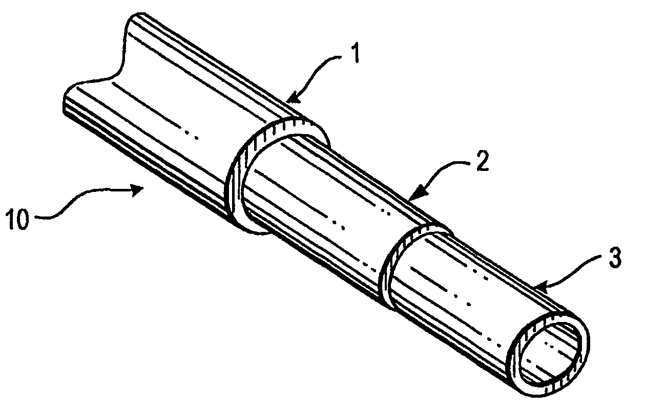
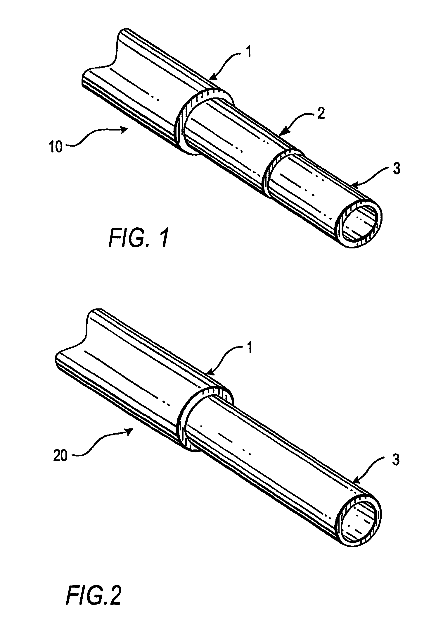
[0015]Referring to FIG. 1, one aspect of the present invention provides a co-extruded tri-layer tubing 10 that includes an outer layer 1 of a polyester, such as a copolyester thermoplastic elastomer (TPE), an inner fluid-contact layer 3, and an intermediate bonding layer 2 of EVA.

[0016]Referring to FIG. 2, another aspect of the present invention provides a dual-layer tubing 20 that eliminates the need for an intermediate bonding layer. This dual-layer tubing 20 includes an outer layer 1 of a polyester, such as a copolyester thermoplastic elastomer (TPE), and an inner fluid-contact layer 3 of a thermoplastic polyurethane (TPU), such as an aromatic or aliphatic polyether-based TPU.

[0017]The polyester outer layer 1 has unexpectedly provided a tubing that is water-clear and flexible without the addition of plasticizers and other additives. The polyester may be a copolyester ether TPE such as Ecdel Elastomer 9966, Ecdel Elastomer 9965, Ecdel Elastomer 9967, and Ecdel development polymer ...


PUM

PropertyMeasurementUnit
thicknessaaaaaaaaaa
thicknessaaaaaaaaaa
thermoplasticaaaaaaaaaa

Abstract

A co-extruded tubing for the administration of intravenous fluids has an outer layer of a polyester. An inner fluid-contact layer may be of a polyethylene or of a thermoplastic polyurethane. Where the inner fluid-contact layer is of polyethylene, an intermediate tie layer of ethylene-vinyl acetate copolymer may be included to prevent delamination.

Description

CROSS-REFERENCE TO RELATED APPLICATIONS[0001]This is a continuation of U.S. patent application Ser. No. 10 / 503,852, now abandoned which is the U.S. National Stage of International Application No. PCT / US2003 / 002019, filed Jan. 23, 2003, which includes a claim for Convention priority based on U.S. patent application Ser. No. 60 / 351,916, filed Jan. 25, 2002.FIELD OF THE INVENTION[0002]The present invention is directed toward a co-extruded tubing for the administration of intravenous fluids that eliminates the need for the inclusion of polyvinyl chloride and plasticizers.BACKGROUND OF RELATED TECHNOLOGY[0003]Plastic tubings are extensively employed in the medical field, particularly for patient analysis and treatment procedures. Various FDA-approved plastics and combinations thereof are used, depending upon the specific properties the intended application demands. The selection of desired plastic materials is further limited by the use of the tubing in the in vivo treatment of human pat...

Claims


Application Information

Patent Timeline
Patent Type & Authority Patents(United States)
IPC IPC(8): F16L11/00A61M5/14A61L29/00A61M25/00A61M39/08B32B1/08B32B27/36F16L11/04
CPCA61M39/08B32B1/08F16L11/20F16L11/04Y10T428/1393Y10T137/2829Y10T137/2836
Inventor DONOHUE, ROBERT JAMESCOGGINS, III, GEORGEBENSON, PERRY
Owner NATVAR HLDG
Learn More