
Environment difference detector

a detector and environment technology, applied in the direction of instruments, specific gravity measurement, furnaces, etc., can solve the problems of slow environmental difference detection speed in the environment difference detector which uses the conventional planar elastic surface wave element, easy damage of sensitive films, etc., to achieve fast and highly accurate measurement, simple configuration of the environment difference detector, and long propagation distance of surface acoustic waves

Active Publication Date: 2010-01-19
YAMANAKA KAZUSHI +1
View PDF3 Cites 10 Cited by
  • Summary
  • Abstract
  • Description
  • Claims
  • Application Information

AI Technical Summary

Benefits of technology

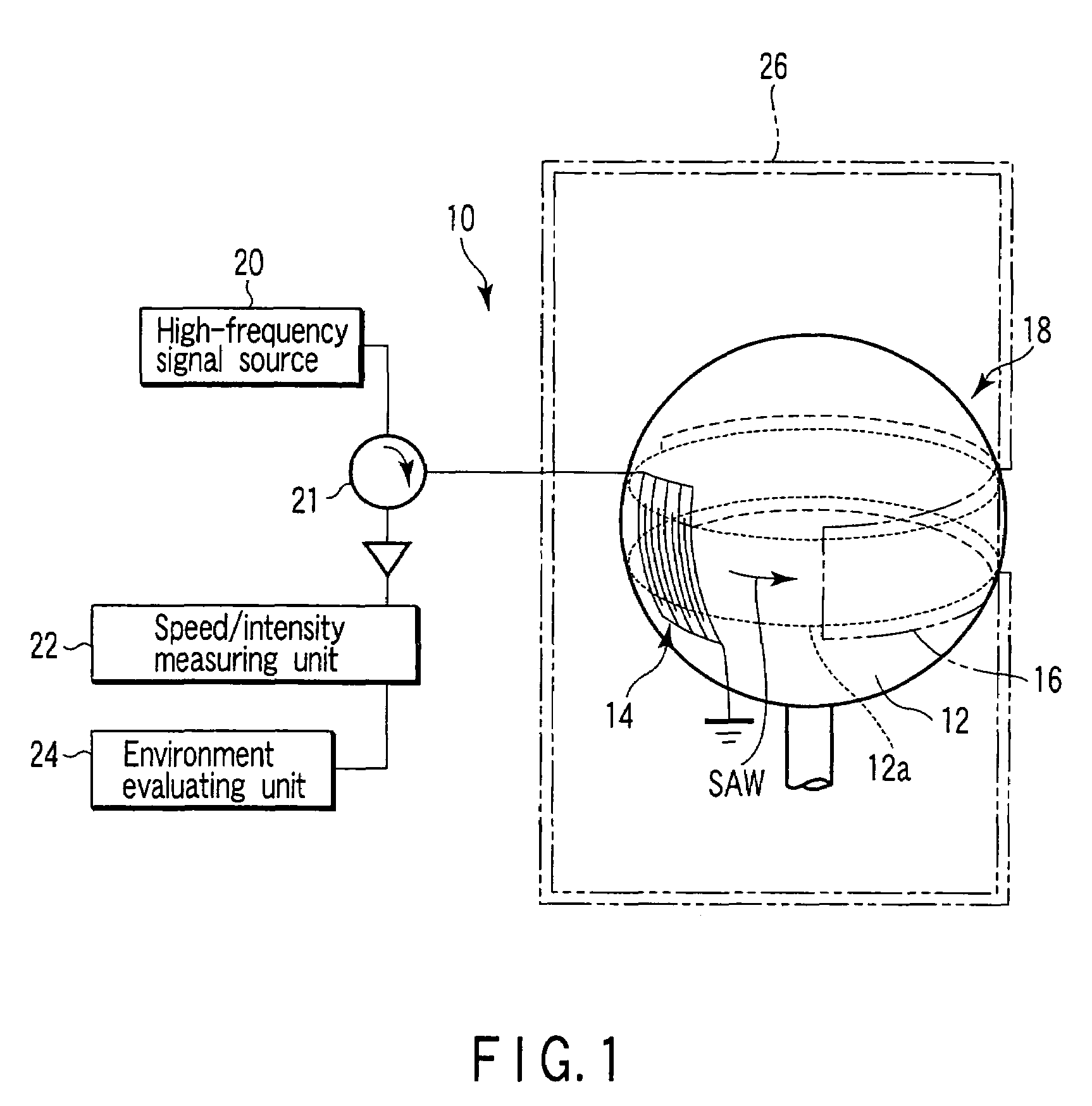
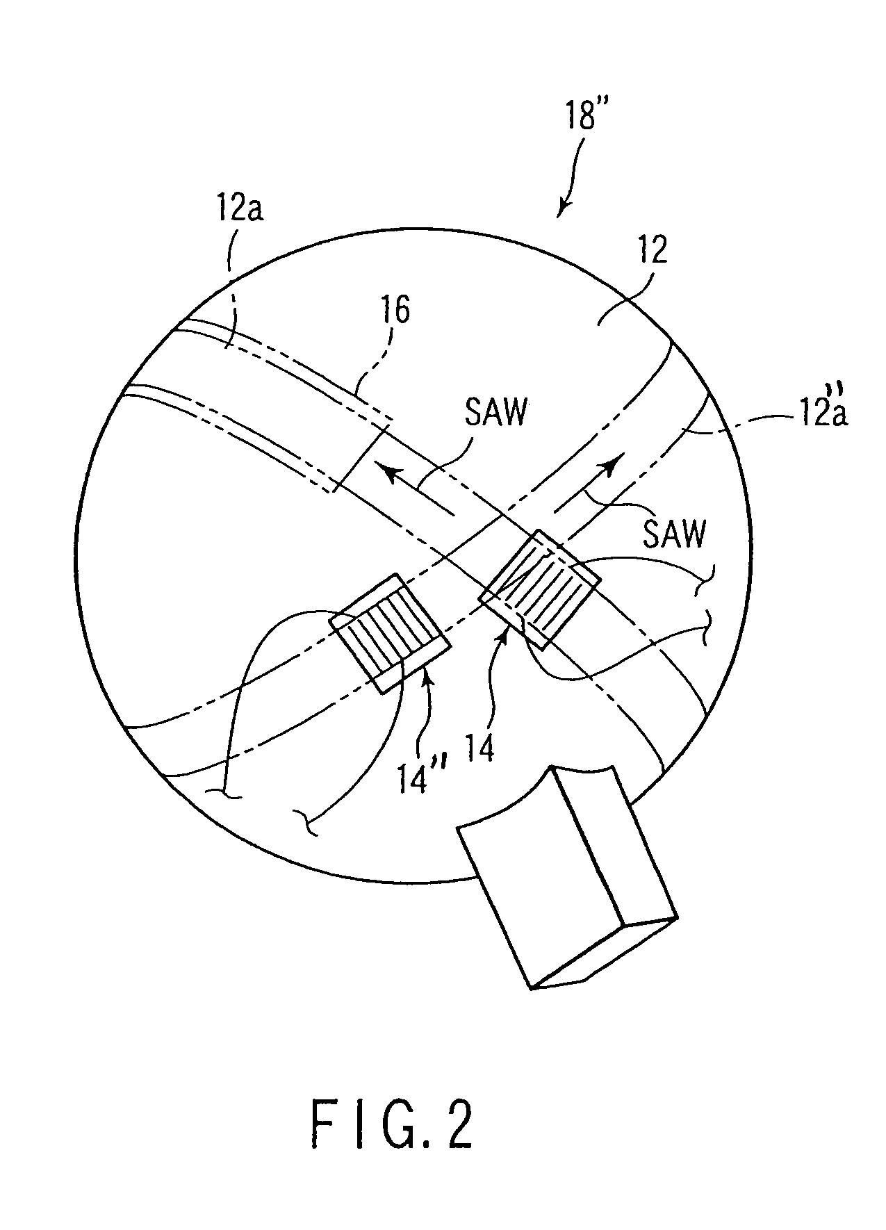
"The present invention provides an environment difference detector that uses an elastic surface wave element equipped with a substrate including a surface having at least one annular and circular path along which a surface acoustic wave circulates, a surface acoustic wave exciting / receiving unit exciting a surface acoustic wave along the circular path, and a sensitive film disposed on at least one part of the circular path to change the elastic nature in accordance with the change in the adjacent environment. The detector can measure the circulating speed and intensity of the surface acoustic wave, which is generated by the surface acoustic wave exciting / receiving unit when the surface acoustic wave circulates along the circular path. The detector can evaluate the environment adjacent to the sensitive film from at least one of the circulating speed and the intensity measured by the speed / intensity measuring unit. The detector is simple in configuration and is less prone to failure. Additionally, the invention provides a hydrogen sensor that can quickly and accurately detect leakage of hydrogen from a fuel cell or the concentration of hydrogen to be used within a short time using the elastic surface wave element."

Problems solved by technology

However, when the thickness of the sensitive film becomes larger, an environment difference detection speed in the environment difference detector which uses the conventional planar elastic surface wave element becomes slow or the sensitive film is easily damaged.

Method used


Image

  • Environment difference detector
  • Environment difference detector
  • Environment difference detector

Examples


example 1

[0096](soundness of the environment difference detector is evaluated by using the intensity of the circulating signal):

[0097]The environment difference detector must be brought into contact with a surrounding environment but it may not be placed under an environment considered at a designing stage. For example, when a user places the detector under an environment where deterioration of the sensitive film and / or that of a wiring line is accelerated, by mistake, the sensitive film and / or the wiring line deteriorates. The deterioration of this kind generally causes an increase in resistance value. When such a change occurs, a changing ratio of the phase value is larger than that of the intensity value, and the deterioration of this kind reduces the intensity. Accordingly, when the intensity takes a value in a range which does not be taken in a sound state, an abnormality of the environment difference detector is determined and a warning is issued.

[0098]As another example, when a foreig...

example 2

[0099](depending on whether the hydrogen concentration is above or low 1.4%, selection is made as to which of the phase value and the intensity value of the electric signal corresponding to the surface acoustic wave is used to measure the hydrogen concentration):

[0100]In a case that the sensitive film is made of palladium, a change of the intensity disappears when the hydrogen concentration is above 1.4%. Thus, when the intensity reaches certain value or more, the hydrogen concentration is calculated by using the phase value of the electric signal corresponding to the surface acoustic wave. Conversely, when a change of the phase disappears and the phase change becomes a certain value or less, the hydrogen concentration is obtained on a basis of the intensity. As a result, the hydrogen concentration is measured more accurately.

[0101]In a case that the sensitive film is made of an alloy containing palladium, the hydrogen concentration which makes the intensity change disappears is dif...

example 3

[0102](hydrogen concentration can be detected highly accurately by making proper selection as to which of the phase and the intensity of the electric signal corresponding to the surface acoustic wave is used to measure the hydrogen concentration when the hydrogen concentration rises or falls)

[0103]When the hydrogen concentration rises with time, following-ability of the intensity change to the change of the hydrogen concentration is better than that of the phase change in the electric signal corresponding to the surface acoustic wave. Accordingly, the hydrogen concentration is detected on a basis of a value of the intensity. Conversely, when the hydrogen concentration falls with time, following-ability of the phase change to the change of the hydrogen concentration is better than that of the intensity change in the electric signal corresponding to the surface acoustic wave. Accordingly, the hydrogen concentration is detected on a basis of a value of the phase. For detecting hydrogen...


PUM

PropertyMeasurementUnit
sizeaaaaaaaaaa
thicknessaaaaaaaaaa
thicknessaaaaaaaaaa

Abstract

An environment difference detector includes an elastic surface wave element equipped with a substrate including a surface having an annular surface acoustic wave circulating path, a surface acoustic wave exciting / receiving unit exciting a surface acoustic wave along the circular path and receiving the circulated surface acoustic wave, and a sensitive film disposed on the circular path to change an elastic nature in accordance with a change in an adjacent environment, a speed / intensity measuring unit measuring a circulating speed and intensity of the surface acoustic wave from an electric signal generated by the unit when the unit receives the circulating surface acoustic wave, and an environment evaluation unit evaluating an environment adjacent to the sensitive film from at least one of the circulating speed and the intensity measured by the unit.

Description

CROSS-REFERENCE TO RELATED APPLICATIONS[0001]This is a Continuation Application of PCT Application No. PCT / JP2005 / 006367, filed Mar. 31, 2005, which was published under PCT Article 21(2) in Japanese.[0002]This application is based upon and claims the benefit of priority from prior Japanese Patent Application No. 2004-108236, filed Mar. 31, 2004, the entire contents of which are incorporated herein by reference.BACKGROUND OF THE INVENTION[0003]1. Field of the Invention[0004]The present invention relates to an environment difference detector for detecting an environment difference.[0005]2. Description of the Related Art[0006]Heretofore, various environment difference detectors for detecting environment differences have been known.[0007]For example, to detect a difference of various gas components, which is an environment difference in an atmosphere, a vapor-phase chemical process or the like, various gas sensors such as a contact combustion type sensor, a semiconductor sensor, and an ...

Claims


Application Information

Patent Timeline
Patent Type & Authority Patents(United States)
IPC IPC(8): G01N29/04G01N29/02G01N29/00G01N29/024G01N29/032G01N29/46
CPCG01N29/022G01N29/024G01N29/032G01N29/2462G01N29/46G01N2291/021G01N2291/0256G01N2291/02809G01N2291/0423
Inventor NAKASO, NORITAKEAKAO, SHINGOYAMANAKA, KAZUSHISIM, DONG YOUNSATOH, ICHITAROMIYAGISHI, TETSUYA
Owner YAMANAKA KAZUSHI
Learn More