Injector

a technology of injector and spring, which is applied in the direction of valve operating means/releasing devices, machines/engines, mechanical apparatus, etc., can solve the problems of increased cost, difficult to make the pressure chamber b>130, and compactness, and achieves easy spring load management and constant spring load

Inactive Publication Date: 2010-01-12
DENSO CORP
View PDF7 Cites 4 Cited by
  • Summary
  • Abstract
  • Description
  • Claims
  • Application Information

AI Technical Summary

Benefits of technology

[0010]It is an object of the present invention to provide an injector that has a pressure chamber with a reduced volume and that is capable of inhibiting fuel leak from the pressure chamber without requiring precise processing.

Problems solved by technology

Therefore, it is difficult to make the pressure chamber 130 compact.
Accordingly, a cost can be increased.

Method used


Image

  • Injector
  • Injector
  • Injector

Examples


first embodiment

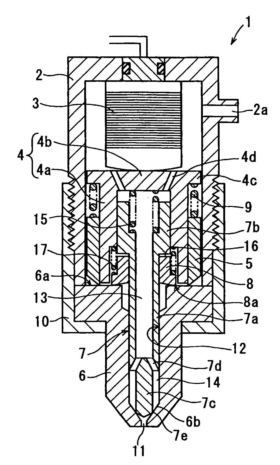
[0037]Referring to FIG. 1, an injector 1 according to the present invention is illustrated. The injector 1 of the present embodiment is a device that is attached to each cylinder of a diesel engine and that injects high pressure fuel, which is supplied from a common rail (not shown), directly into a combustion chamber in the cylinder, for example. As shown in FIG. 1, the injector 1 includes a valve housing 2, a piezoelectric actuator 3, a pressurizing piston 4, an outer sleeve 5, a valve body 6, a needle 7, an inner sleeve 8 and the like.

[0038]The valve housing 2 defines a sealed space between the valve housing 2 and the valve body 6 and is formed with a fuel inlet 2a connected to the common rail through a fuel pipe (not shown). The sealed space is filled with high pressure fuel flowing in from the fuel inlet 2a.

[0039]The piezoelectric actuator 3 is a common actuator having a capacitor structure of alternately laminated piezoelectric ceramic layers such as PZT (lead zirconate titan...

third embodiment

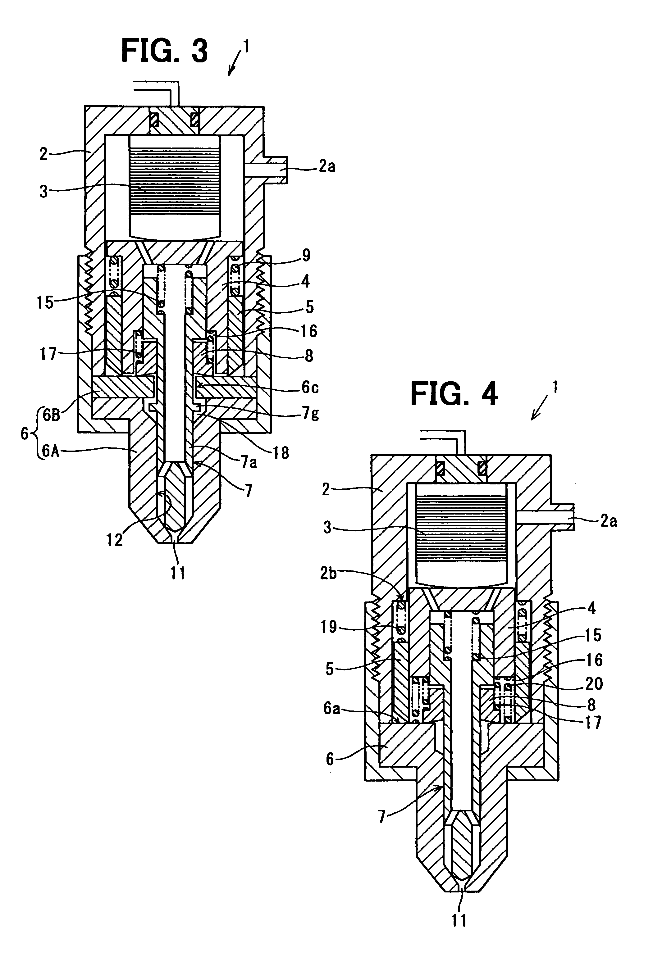
[0066]Next, an injector 1 according to the present invention will be described with reference to FIG. 4. FIG. 4 is a sectional view showing the injector 1 according to the present embodiment. The injector 1 of the present embodiment is an example providing a spring 19 for biasing the outer sleeve 5 toward the valve body 6 side and providing an engagement face for the spring 19 to the valve housing 2 as shown in FIG. 4. That is, one end of the spring 19 is engaged with a step 2b formed on the inner periphery of the valve housing 2, and the other end of the spring 19 is engaged with an axial rear end face of the outer sleeve 5.

[0067]A spring 20 for pushing back the pressurizing piston 4 when the energization to the piezoelectric actuator 3 is stopped is located between the pressurizing piston 4 and the rear end face 6a of the valve body 6.

[0068]In the injector 1 according to the first embodiment, the spring 9 (refer to FIG. 1) is located between the flange section 4c of the pressurizi...


PUM


Abstract

An injector has an inner sleeve between a needle pressure receiving face of a needle and a rear end face of a valve body. The inner sleeve is slidably fitted to an outer periphery of a middle shaft section of the needle. The inner sleeve receives a reaction force of a spring located between the inner sleeve and a pressurizing piston, so an axial tip end (edge section) of the inner sleeve is pressed against the rear end face to achieve close contact therebetween. Thus, a volume of a pressure chamber can be reduced, so a valve opening force for lifting the needle can be acquired efficiently. Accordingly, injection of a large flow rate can be performed by increasing a lift amount of the needle and also quick lifting of the needle can be performed.

Description

CROSS REFERENCE TO RELATED APPLICATION[0001]This application is based on and incorporates herein by reference Japanese Patent Application No. 2007-54022 filed on Mar. 5, 2007.BACKGROUND OF THE INVENTION[0002]1. Field of the Invention[0003]The present invention relates to an injector that performs injection supply of high pressure fuel to a combustion chamber of an internal combustion engine.[0004]2. Description of Related Art[0005]An injector using an electromagnetic valve as an actuator is commonly used. In order to realize a large flow rate and high response, an injector using a piezoelectric actuator with a large generative force and high response is proposed. For example, an injector described in Patent document 1 (International Publication No. 2005 / 075811) has a piezoelectric actuator 100 that makes a displacement when voltage is applied thereto, a pressurizing piston 110 driven by the piezoelectric actuator 100, an outer sleeve 120 for slidably holding an outer periphery of th...

Claims


Application Information

Patent Timeline
Patent Type & Authority Patents(United States)
IPC IPC(8): B05B1/08F02M61/20
CPCF02M51/0603F02M2200/704
Inventor MOCHIZUKI, KOUICHIKUROYANAGI, MASATOSHI
Owner DENSO CORP
Why Eureka
Try Eureka