Diffraction element and optical pick-up apparatus having the same

a pickup apparatus and optical technology, applied in the field of optical pickup apparatus, can solve the problems of not being able to compensate for the dc offset of different types of disks, the dpp method is basically limited to a single track pitch, and the sub-beam cannot always be formed in the same groove as the main beam, etc., to achieve precise tracking control

Inactive Publication Date: 2010-01-05
SAMSUNG ELECTRONICS CO LTD
View PDF19 Cites 2 Cited by
  • Summary
  • Abstract
  • Description
  • Claims
  • Application Information

AI Technical Summary

Benefits of technology

[0012]An aspect of the present invention is to solve at least the above problems and / or disadvantages and to provide at least the advantages described below. Accordingly, an aspect of the present invention is to provide a diffraction element for an optical pick-up which can perform precise tracking control and an optical pick-up apparatus using the diffraction element.

Problems solved by technology

When the DPP method is used for disks with different specifications for track pitch, however, the sub-beams cannot always be formed in the same groove as the main beam.
That is, the DPP method is basically limited to a single track pitch, and cannot be used to compensate for DC offset of different types of disks.
However, in such a device, the respective regions 12, 14, and 16 have grooves that are offset with respect to each other, and a phase difference of ±90° occurs between the main beam MB and the sub-beams SB, thereby causing interference between the beams.
As a result, the TE signal reflected from the disk D and detected by a light receiving element has errors, which lowers tracking precision.

Method used


Image

  • Diffraction element and optical pick-up apparatus having the same
  • Diffraction element and optical pick-up apparatus having the same
  • Diffraction element and optical pick-up apparatus having the same

Examples


Embodiment Construction

[0031]The matters defined in the description such as a detailed construction and elements are provided to assist in a comprehensive understanding of the embodiments of the invention. Accordingly, those of ordinary skill in the art will recognize that various changes and modifications of the embodiments described herein can be made without departing from the scope and spirit of the invention. Also, descriptions of well-known functions and constructions are omitted for clarity and conciseness.

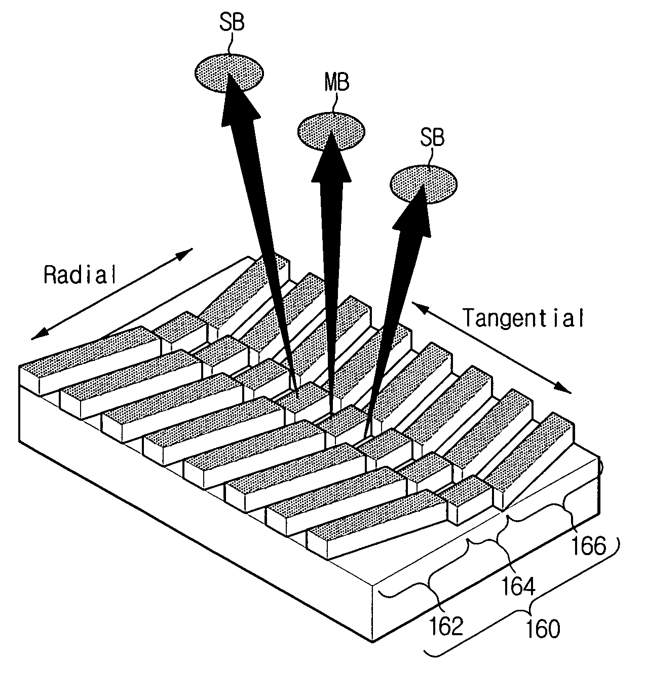
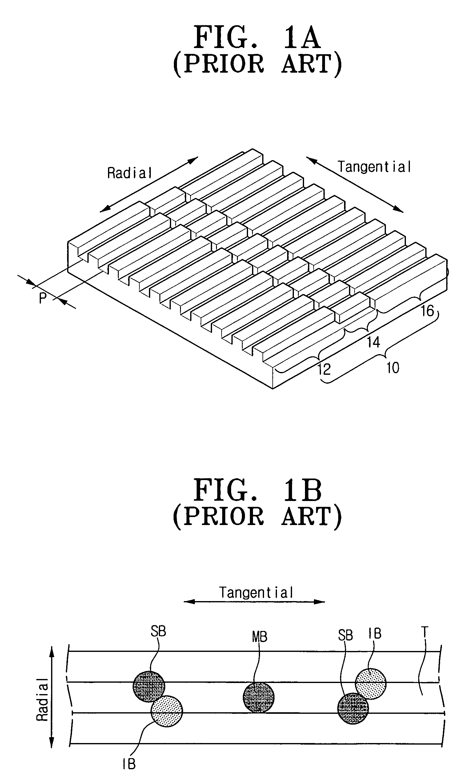
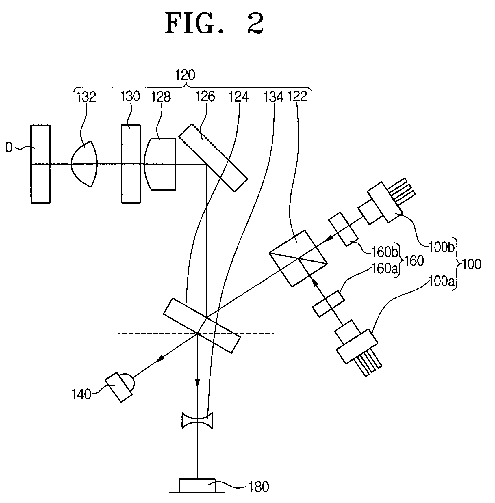
[0032]Referring to FIG. 2, an optical pick-up apparatus according to an exemplary embodiment of the present invention includes a light source 100, an optical system 120, a monitoring light detector (FPD, or front photo diode) 140, a diffraction element 160, and a light detector (PDIC, or photo diode integrated circuit) 180.

[0033]The light source 100 includes a first light source 100a for a DVD (Digital Versatile Disk) and a second light source 100b for a CD (Compact Disk). Preferably, the light s...


PUM

PropertyMeasurementUnit
widthaaaaaaaaaa
wavelengthaaaaaaaaaa
at wavelengthaaaaaaaaaa

Abstract

A diffraction element for an optical pick-up apparatus is capable of precisely controlling the tracking of the pick-up apparatus. The diffraction element includes a diffraction grating divided into a first, a second, and a third region. The second region is located between the first and third regions. Any one of the first region and the third region is inclined at a predetermined angle θ with respect to the second region.

Description

CROSS-REFERENCE TO RELATED APPLICATIONS[0001]This application claims the benefit under 35 U.S.C. §119(a) of Korean Patent Application No. 2005-5108, filed on Jan. 19, 2005, in the Korean Intellectual Property Office, the entire content of which is hereby incorporated by reference.BACKGROUND OF THE INVENTION[0002]1. Field of the Invention[0003]The present invention relates to an optical pick-up apparatus. More particularly, the present invention relates to a diffraction element that improves tracking control, and an optical pick-up apparatus that uses the diffraction element.[0004]2. Description of the Related Art[0005]An optical pick-up apparatus is used in various devices such as compact disk players (CDs), digital versatile disk players (DVDs), CD-ROM drives, and similar device to read and write information from an optical recording medium (such as an optical disk) without contacting the medium. To write information, the optical pick-up irradiates the laser beam on the surface of ...

Claims


Application Information

Patent Timeline
Patent Type & Authority Patents(United States)
IPC IPC(8): G11B7/00G11B7/135
CPCG11B7/0903G11B7/1353G11B2007/0006A47J37/0676F24C7/04F24C15/24
Inventor KIM, BONG-GIPARK, SEONG-SUHONG, JUNG-WOO
Owner SAMSUNG ELECTRONICS CO LTD
Why Eureka
Try Eureka