
Moisture separator and reheater

a technology of moisture separator and reheater, which is applied in the direction of steam separation arrangement, lighting and heating apparatus, machines/engines, etc., can solve the problems of manufacturing cost and operating cost, instability of flow, and mal-distribution of heating medium (steam) inside the tube, and achieve the effect of minimizing parasitic pressure loss

Inactive Publication Date: 2010-01-05
YOUSOUFIAN HRANT H
View PDF4 Cites 0 Cited by
  • Summary
  • Abstract
  • Description
  • Claims
  • Application Information

AI Technical Summary

Benefits of technology

"The present invention is a configuration that includes a circuit for the cycle steam in relation to the moisture separator and reheaters. This configuration is designed to optimize the extraction of power from the cycle steam while minimizing the costs of manufacturing and operating the system. The objective is to achieve the highest power extraction while balancing the economic effects of parasitic pressure losses and maximum heat exchange."

Problems solved by technology

The aforementioned has given rise to problems of mal-distribution of the heating medium (steam) inside the tubes and instability of flow as well as binding of the tubes in the vicinity of the U-bend.
These problems have been mitigated by elaborate and costly schemes affecting manufacturing cost as well as operating cost.
The arrangement of various components through which cycle steam flows has been subject to uncontrolled or excessive pressure loss of a parasitic nature.

Method used


Image

  • Moisture separator and reheater
  • Moisture separator and reheater
  • Moisture separator and reheater

Examples


Embodiment Construction

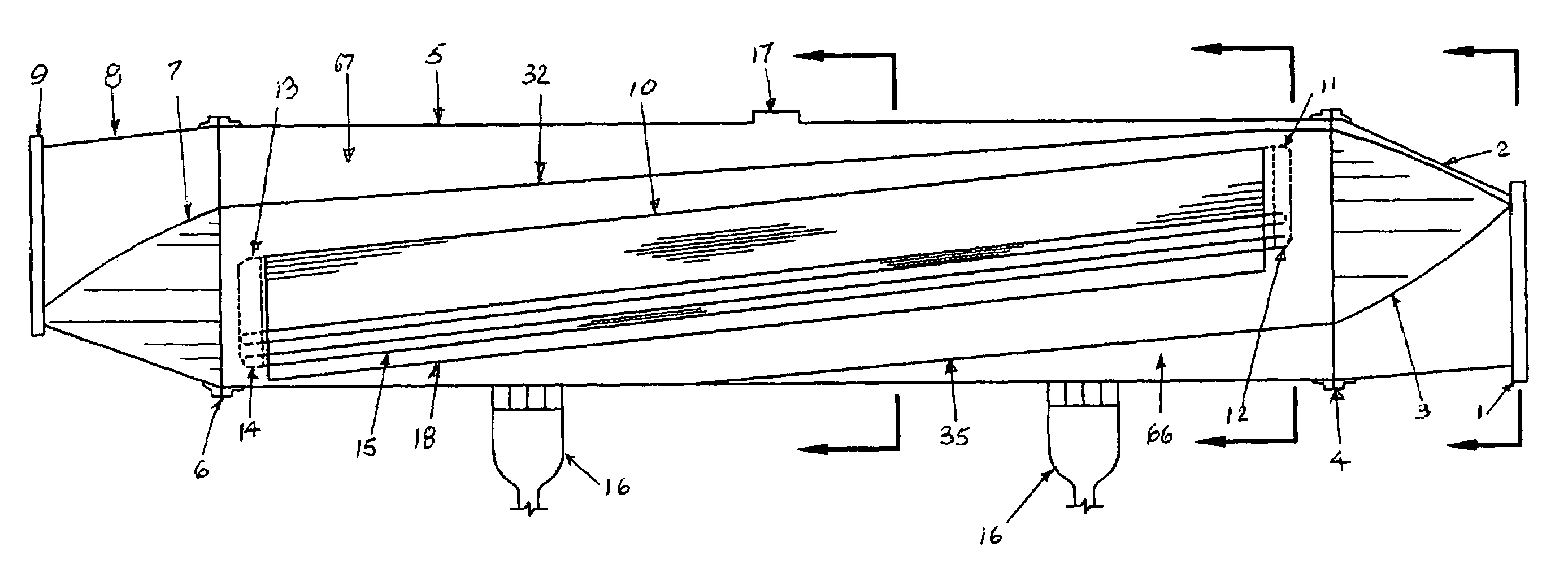
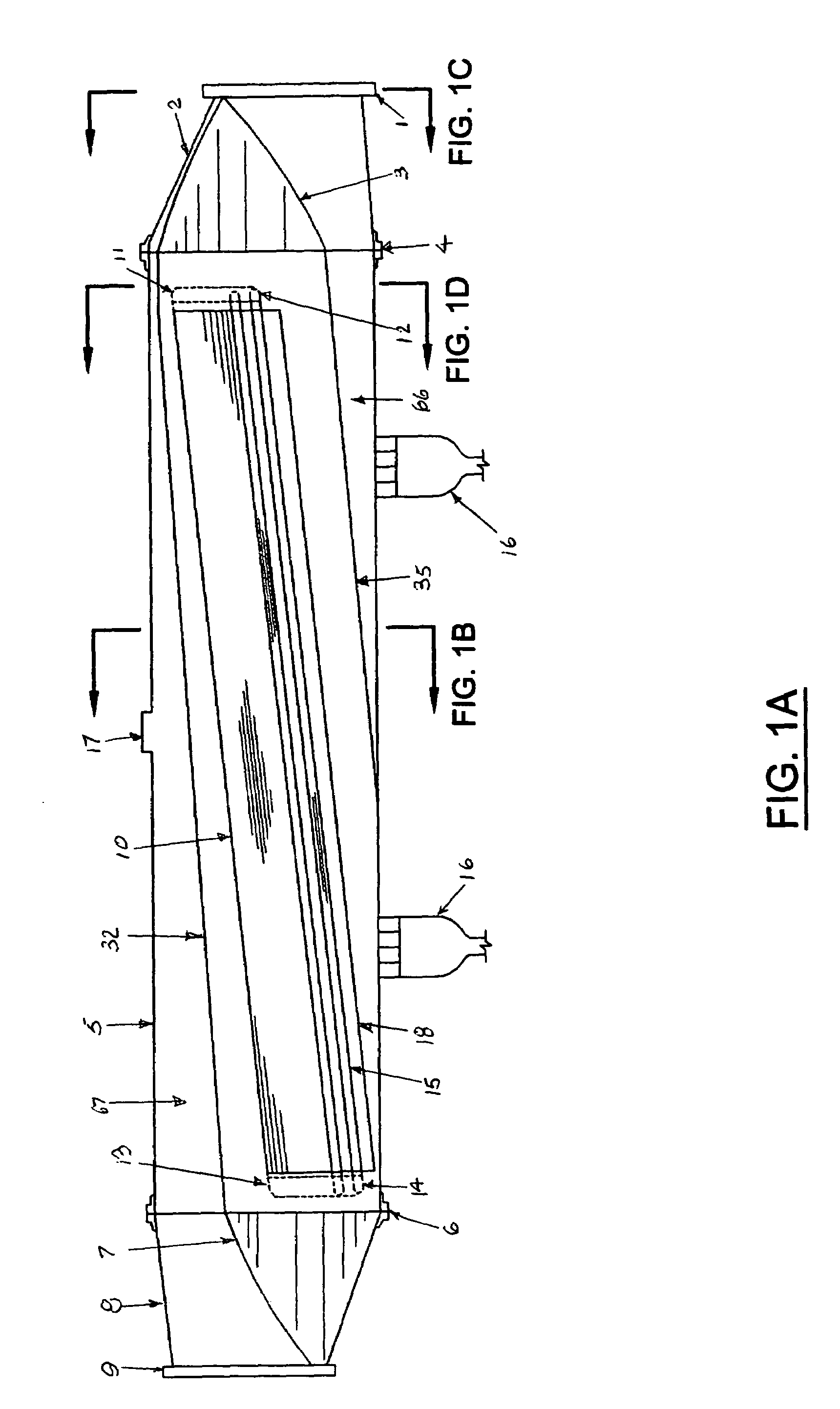
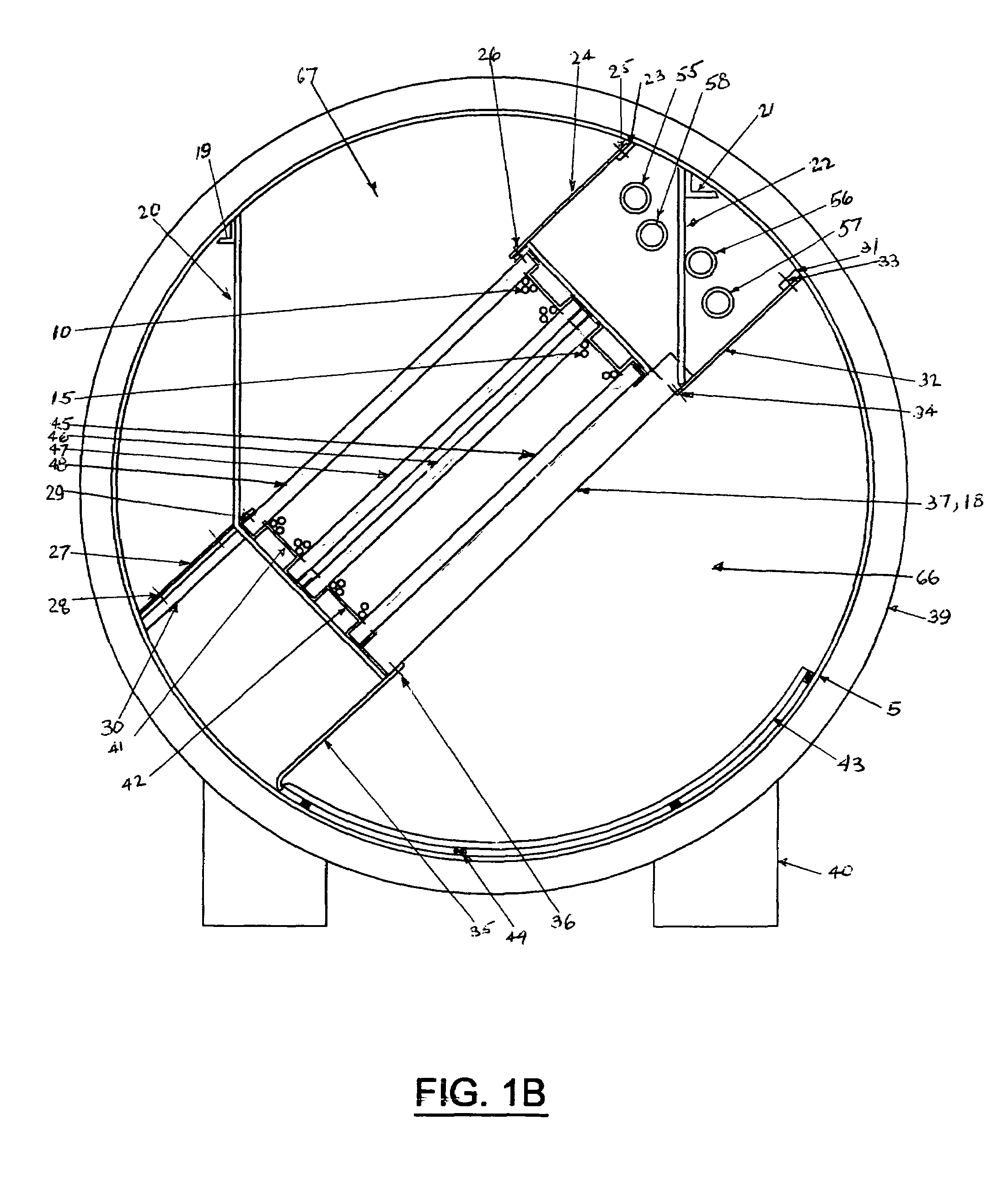
[0013]FIG. 1A shows the principal features of the moisture separator and reheater. The steam for the turbine, referred to as cycle steam, enters at the flanged connection, 1, passes into the offset truncated cone, 2, and guided by an internal baffle, 3, to the entry side of the dryer, 18, along a tapered duct, 66. The cycle steam exits the dryer and passes, successively through reheaters, of which two are shown, and exits into a tapered duct 67. The cycle steam then flows into the truncated, offset, exit cone, 8, thence to a cylindrical duct connected to flange, 9. At the top of the final table bundle of the reheaters, 13, baffle 7 serves a similar function as entry baffle, 3. The cylindrical shell, 5, provides the continuing pressure boundary for the cycle steam. Item 17 may serve as a man-way, or other use, for access to tapered duct, 67. A nozzle, similar to 17 (not shown) may be provided into shell 5 for convenient access into tapered duct 66. FIG. 1B is a cross section at a loc...


PUM


Abstract

Contrasted to the prior art, the present invention presents a path for the cycle steam having the fewest possible changes in direction to minimize parasite pressure losses. This invention accommodates proportioning the flow areas of the moisture separator—reheater(s) assembly to optimize performance of extracting the maximum energy from the cycle steam and in view of the economics of first cost and operating cost. The reheater tubes are straight, not U-tubed, and sloped towards the reheat steam condensate discharge. It utilizes an internal baffle in the reheating steam manifold, features which would mitigate tube binding, steam distribution to the tube bundles, flow oscillations, etc. which are expensive and difficult to alleviate.

Description

BACKGROUND OF INVENTIONS[0001]The subject of this invention is utilized in the steam cycle of a nuclear power plant. The heat exchangers in moisture separator and reheaters have, typically, employed a U-tube bundle for each stage of reheat. The aforementioned has given rise to problems of mal-distribution of the heating medium (steam) inside the tubes and instability of flow as well as binding of the tubes in the vicinity of the U-bend. These problems have been mitigated by elaborate and costly schemes affecting manufacturing cost as well as operating cost. The arrangement of various components through which cycle steam flows has been subject to uncontrolled or excessive pressure loss of a parasitic nature. The current invention effectively claims to obviate or mitigate the aforementioned problems by accommodating a means to optimize the physical arrangements of drying and reheating cycle steam.BRIEF SUMMARY OF THE INVENTION[0002]The configuration of the present invention incorporat...

Claims


Application Information

Patent Timeline
Patent Type & Authority Patents(United States)
IPC IPC(8): F01K7/34
CPCF22B37/266
Inventor YOUSOUFIAN, HRANT H.
Owner YOUSOUFIAN HRANT H
Learn More