
Arc fault circuit interrupter and series arc fault detection method using plural high frequency bands

a fault detection and circuit interrupter technology, applied in the field of circuit interrupters, can solve the problems of poor electrical connection, small reduction of load current, and inability to overload the capability of a conventional circuit breaker

Active Publication Date: 2009-12-15
EATON INTELLIGENT POWER LTD
View PDF12 Cites 41 Cited by
  • Summary
  • Abstract
  • Description
  • Claims
  • Application Information

AI Technical Summary

Benefits of technology

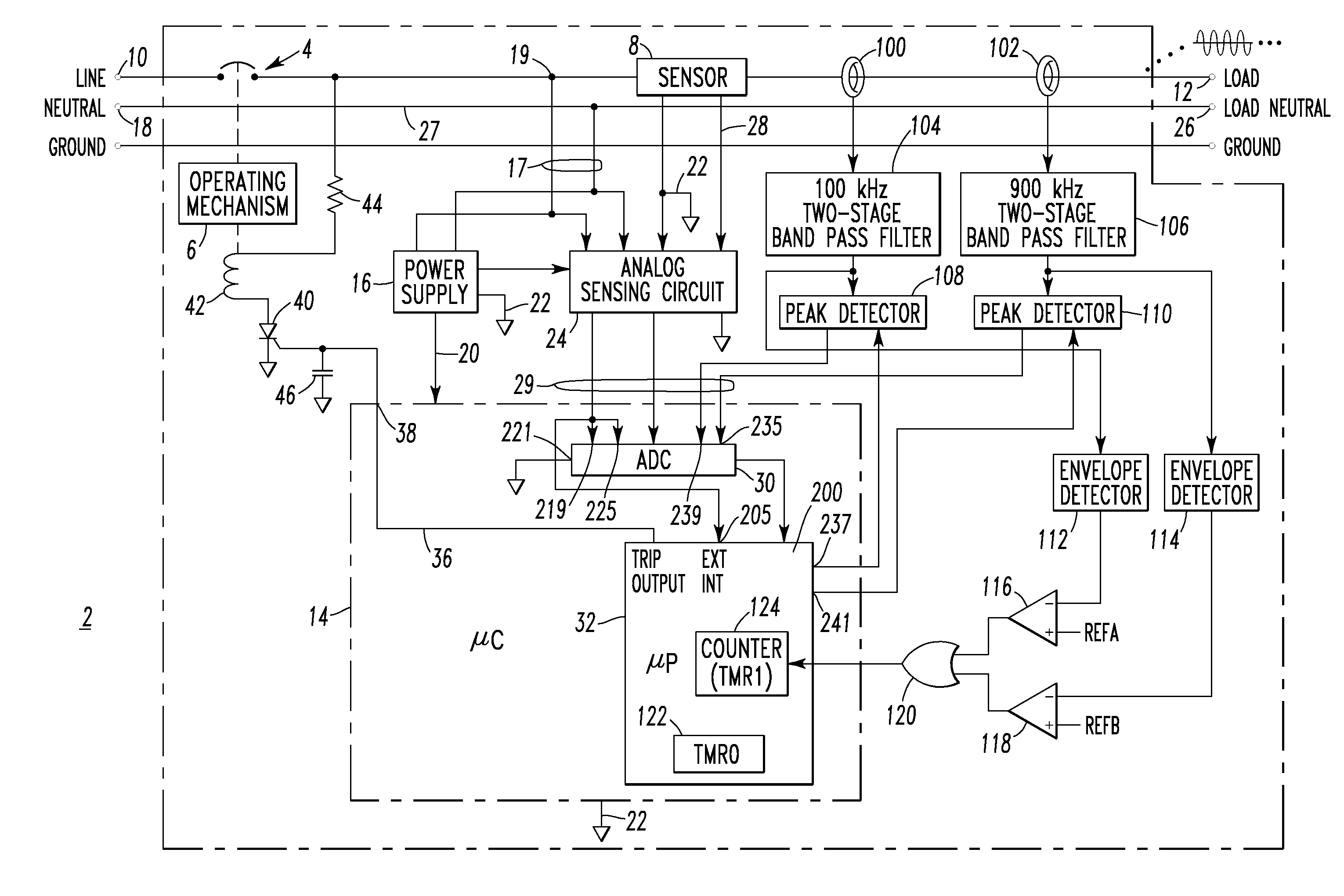
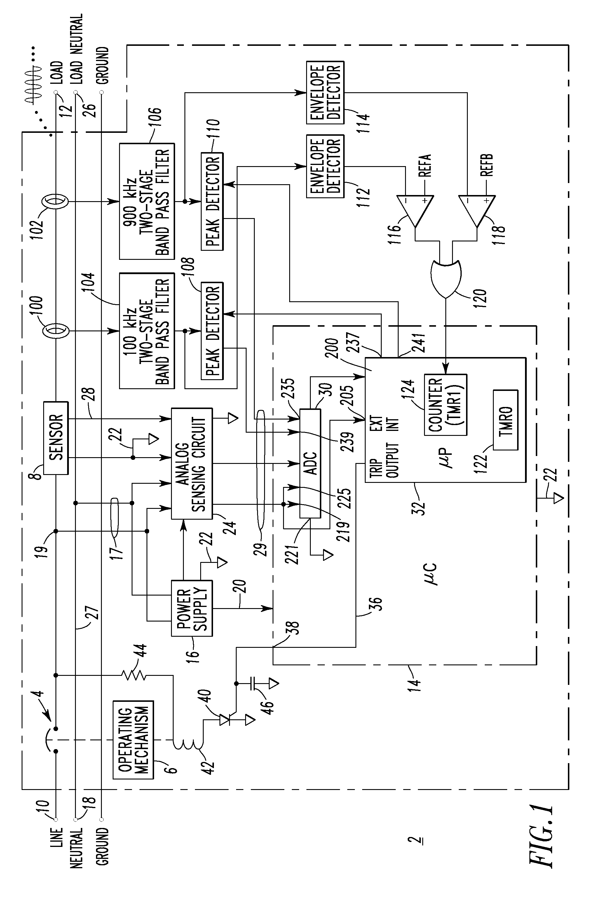
The invention provides improvements in detecting series arc faults in an alternating current power circuit. The improvements involve using two band pass filters with different ranges of frequencies to capture the current sensed through the circuit. The first filter has a range of frequencies that includes the first half-cycle of the current, while the second filter has a range of frequencies that includes the second half-cycle. The first and second filters output separate signals that are used to detect peak current values and tallies, which are used to determine the presence of a series arc fault. The processor used in the invention can also disable the series arc detection when the sensed current exceeds a predetermined threshold. The technical effects of the invention include improved accuracy in detecting series arc faults and improved ability to disable the detection when needed.

Problems solved by technology

During sporadic arc fault conditions, the overload capability of a conventional circuit breaker will not function since the root-mean-squared (RMS) value of the fault current is too small to activate the automatic magnetic trip circuit.
Examples of a series arc are a broken wire where the ends of the broken wire are close enough to cause arcing, or a relatively poor electrical connection.
In fact, a series arc fault may result in a slight reduction in load current and not be detected by the normal overload and overcurrent protection of conventional protection devices.
A problem associated with this technology is that it highly depends on the electric loads that can sometimes generate false arc fault signatures at the fundamental frequency as well as at other relatively low frequencies.
During the time the arc is conducting current, it produces wideband, high-frequency noise.

Method used


Image

  • Arc fault circuit interrupter and series arc fault detection method using plural high frequency bands
  • Arc fault circuit interrupter and series arc fault detection method using plural high frequency bands
  • Arc fault circuit interrupter and series arc fault detection method using plural high frequency bands

Examples


example 1

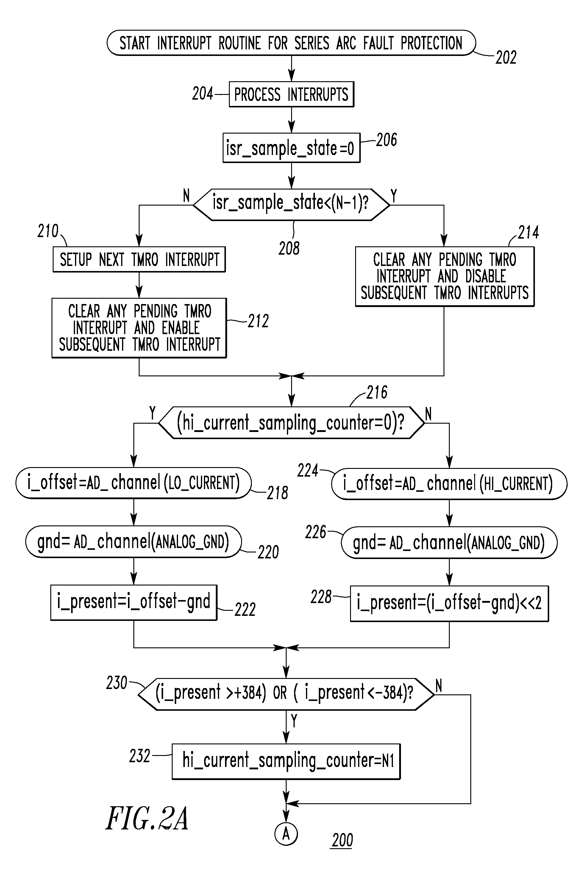
[0045]Certain loads generate high frequency noise that has significantly high moving average baselines, especially during their start up. In order to eliminate nuisance tripping caused by these type of loads, series arc detection is preferably disabled for a predetermined time (e.g., without limitation, 1 second) if the first moving average or the second moving average is greater than a predetermined value (e.g., without limitation, for a chop saw, the moving average goes up significantly; the predetermined values for the first and second moving averages can be 160 and 140, respectively).

example 2

[0046]Line cycle (e.g., 60 Hz) wave shape information is preferably employed to provide adequate trip response to clearing time tests. This means that the trip response should be based on the load (e.g., 60 Hz) current waveform (not just the current peak value, but rather the rms value since some loads, such as a dimmer, may have a relatively high peak current value, but a relatively small rms value) and the required tripping time at different current levels in UL 1699. This checks the rms current value or the average rms current value of several cycles and finds the required tripping time. If the series chaos accumulator (series_accum of step 328 of FIG. 2E1) is greater than a suitable trip threshold (e.g., without limitation, the tripping bucket level of 300 counts) before the required tripping time (e.g., without limitation, 1 second at 5 ARMS), then wait without tripping the circuit breaker 2 until a predefined time (e.g., without limitation, 100 mS for this example) before the ...

example 3

[0063]Preferably, the μP 32 of FIG. 1 is structured to introduce “jitter” in the otherwise periodic data sampling times of the outputs of the peak detectors 108,110 as sensed through the respective ADC channels 239,235. One approach to eliminate repetitive high frequency signals generated by certain loads, such as dimmers, is to check if the variation between two adjacent peak values falls within a predefined range, such as 5%. If the variation falls within the predefined range, then the detected peak signal will not be counted as an arc fault generated signal. The “jitter” eliminates false series arc indication due to consistent large variations between two adjacent peak values caused by the periodic timer interrupt from the μP timer TMR0122. When the circuit breaker 2 protects a dimmer (not shown) and an incandescent lighting load (not shown), the high frequency pulse associated with the turn-on of dimmer current occasionally coincides with the time when the high frequency peak de...


PUM


Abstract

A circuit interrupter includes band pass filters cooperating with a current sensor to output bands having different, non-overlapping ranges of frequencies, peak detectors cooperating with the filters to detect corresponding peak current values, envelope detectors cooperating with the filters to detect corresponding occurrences from the bands being within corresponding predetermined magnitude ranges, a counter counting the occurrences, and a processor providing and disabling series arc detection when sensed current is greater than a first predetermined value. The processor determines tallies responsive to peak current values exceeding corresponding thresholds, determines series arcing from sensed current being less than the first predetermined value for a predetermined time, the tally for a current half-cycle being nonzero, and a count for the current half-cycle being different than the count for an immediately previous half-cycle of like polarity by at least a second predetermined value. A series chaos accumulator is increased responsive to series arcing.

Description

CROSS-REFERENCE TO RELATED APPLICATION[0001]This application is related to commonly assigned, concurrently filed:[0002]U.S. patent application Ser. No. 11 / 679,281, filed Feb. 27, 2007, entitled “Arc Fault Circuit Interrupter And Method Of Parallel And Series Arc Fault Detection”.BACKGROUND OF THE INVENTION[0003]1. Field of the Invention[0004]This invention pertains generally to circuit interrupters and, more particularly, to arc fault circuit interrupters. The invention also relates to methods of detecting series arc faults.[0005]2. Background Information[0006]Circuit breakers are used to protect electrical circuitry from damage due to an overcurrent condition, such as an overload condition or a relatively high level short circuit or fault condition. In small circuit breakers, commonly referred to as miniature circuit breakers, used for residential and light commercial applications, such protection is typically provided by a thermal-magnetic trip device. This trip device includes a ...

Claims


Application Information

Patent Timeline
Patent Type & Authority Patents(United States)
IPC IPC(8): H02H3/00H02H9/08H02H3/08H02H7/26H02H9/02
CPCH02H1/0015H02H1/04
Inventor ZHOU, XINSHEA, JOHN J.PARKER, KEVIN L.MILLER, THEODORE J.
Owner EATON INTELLIGENT POWER LTD
Learn More