Differential ring oscillator
a technology of ring oscillator and oscillator, which is applied in the direction of oscillator generator, pulse automatic control, logic circuit pulse generation, etc., can solve the problems of blocking the reduction of power consumption of microcomputers, no cost merit above the way of providing an external quartz oscillator to obtain an operation clock signal for a microcomputer, etc., to achieve sufficient oscillation frequency precision, improve the yield of semiconductor integrated circuits, and excellent robustness
- Summary
- Abstract
- Description
- Claims
- Application Information
AI Technical Summary
Benefits of technology
Problems solved by technology
Method used
Image
Examples
embodiment 1
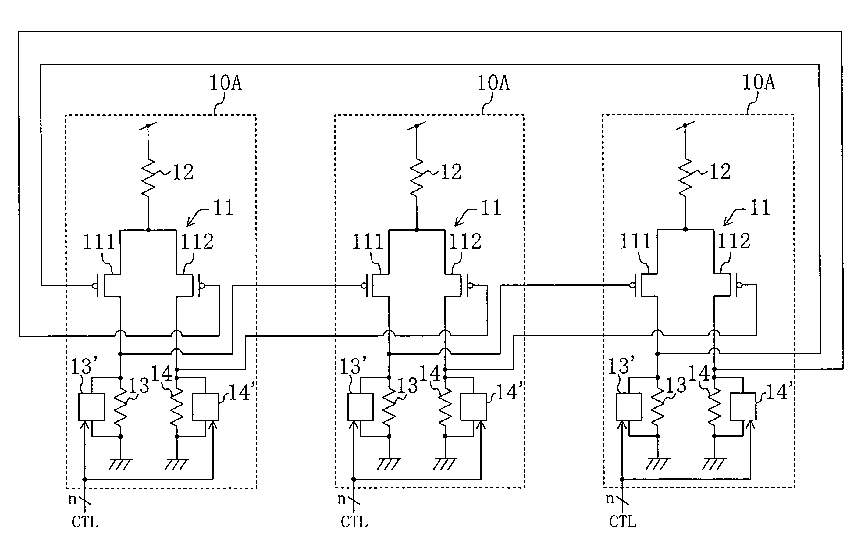
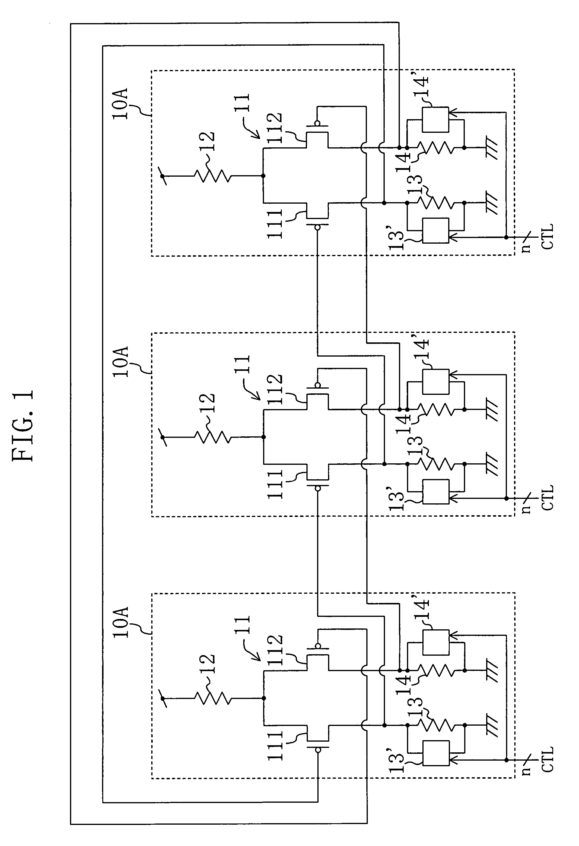
[0039]FIG. 1 shows a configuration of a ring oscillator of Embodiment 1. The ring oscillator of this embodiment is composed of three differential amplifier circuits 10A connected in a loop. Each of the differential amplifier circuits 10A includes a differential transistor pair 11, resistances 12, 13 and 14 and passive circuits 13′ and 14′. The differential transistor pair 11 is composed of PMOS transistors 111 and 112 whose sources are connected to each other and whose gates receive a differential signal. The resistance 12 is connected to the junction point of the PMOS transistors 111 and 112 at one terminal and to the power supply voltage node at the other terminal. The resistance 13 is connected to the drain of the PMOS transistor 111 at one terminal and to the ground voltage node at the other terminal. The resistance 14 is connected to the drain of the PMOS transistor 112 at one terminal and to the ground voltage node at the other terminal. The passive circuits 13′ and 14′ are re...
embodiment 2
[0046]FIG. 5 shows a configuration of a ring oscillator of Embodiment 2 of the present invention. The ring oscillator of this embodiment is composed of three differential amplifier circuits 10B connected in a loop. Each of the differential amplifier circuits 10B is different from the differential amplifier circuit 10A shown in FIG. 1 in that the passive circuits 13′ and 14′ are omitted and instead a passive circuit 12′ is provided in parallel with the resistance 12.
[0047]The passive circuit 12′ can be made of the variable resistance circuit shown in FIG. 3. With the passive circuit 12′ made of the variable resistance circuit being connected in parallel with the resistance 12, the combined resistance value becomes small. This increases the capacity of current supply to the resistances 13 and 14, and thus the oscillation frequency of the ring oscillator becomes higher. The oscillation frequency of the ring oscillator will further become higher as the resistance value of the passive ci...
embodiment 3
[0049]FIG. 6 shows a configuration of a ring oscillator of Embodiment 3 of the present invention. The ring oscillator of this embodiment is composed of three differential amplifier circuits 10C connected in a loop. Each of the differential amplifier circuits 10C is different from the differential amplifier circuit 10A shown in FIG. 1 in that NMOS transistors 15 and 16 are respectively provided in place of the circuit portion composed of the resistance 13 and the passive circuit 13′ and the circuit portion composed of the resistance 14 and the passive circuit 14′ and that a resistance 17 and a passive circuit 17′ are newly provided to be connected to the junction point of the PMOS transistor 111 and the NMOS transistor 15 at one terminal and to the junction point of the PMOS transistor 112 and the NMOS transistor 16 at the other terminal.
[0050]A same signal is supplied to the gate of the NMOS transistor 15 and the gate of the PMOS transistor 111. Likewise, a same signal is supplied t...
PUM
 Abstract
Description
Claims
Application Information
 - R&D
- Intellectual Property
- Life Sciences
- Materials
- Tech Scout
- Unparalleled Data Quality
- Higher Quality Content
- 60% Fewer Hallucinations
Browse by: Latest US Patents, China's latest patents, Technical Efficacy Thesaurus, Application Domain, Technology Topic, Popular Technical Reports.
© 2025 PatSnap. All rights reserved.Legal|Privacy policy|Modern Slavery Act Transparency Statement|Sitemap|About US| Contact US: help@patsnap.com


