Pneumatic tire and manufacturing method of the same

a pneumatic tire and manufacturing method technology, applied in the field of pneumatic tires, can solve the problems of deterioration of time required for winding, and deterioration of production efficiency, so as to improve the outer appearance quality of tires, shorten the winding time, and increase production efficiency

Inactive Publication Date: 2009-12-08
SUMITOMO RUBBER IND LTD
View PDF16 Cites 5 Cited by
  • Summary
  • Abstract
  • Description
  • Claims
  • Application Information

AI Technical Summary

Benefits of technology

[0008]Accordingly, an object of the present invention is to provide a pneumatic tire which can simultaneously wind respective rubber strips, can shorten a winding time so as to increase a production efficiency, can inhibit a turbulence of a rubber strip at a time of winding up a protruding portion, and can improve an outer appearance quality of the tire, and a manufacturing method of the same.

Problems solved by technology

Accordingly, a time is required for winding, and a production efficiency is deteriorated.
Accordingly, the turbulence is generated in winding the rubber strip, and there is generated a tendency that an outer appearance quality of the tire is deteriorated.

Method used


Image

  • Pneumatic tire and manufacturing method of the same
  • Pneumatic tire and manufacturing method of the same
  • Pneumatic tire and manufacturing method of the same

Examples


Embodiment Construction

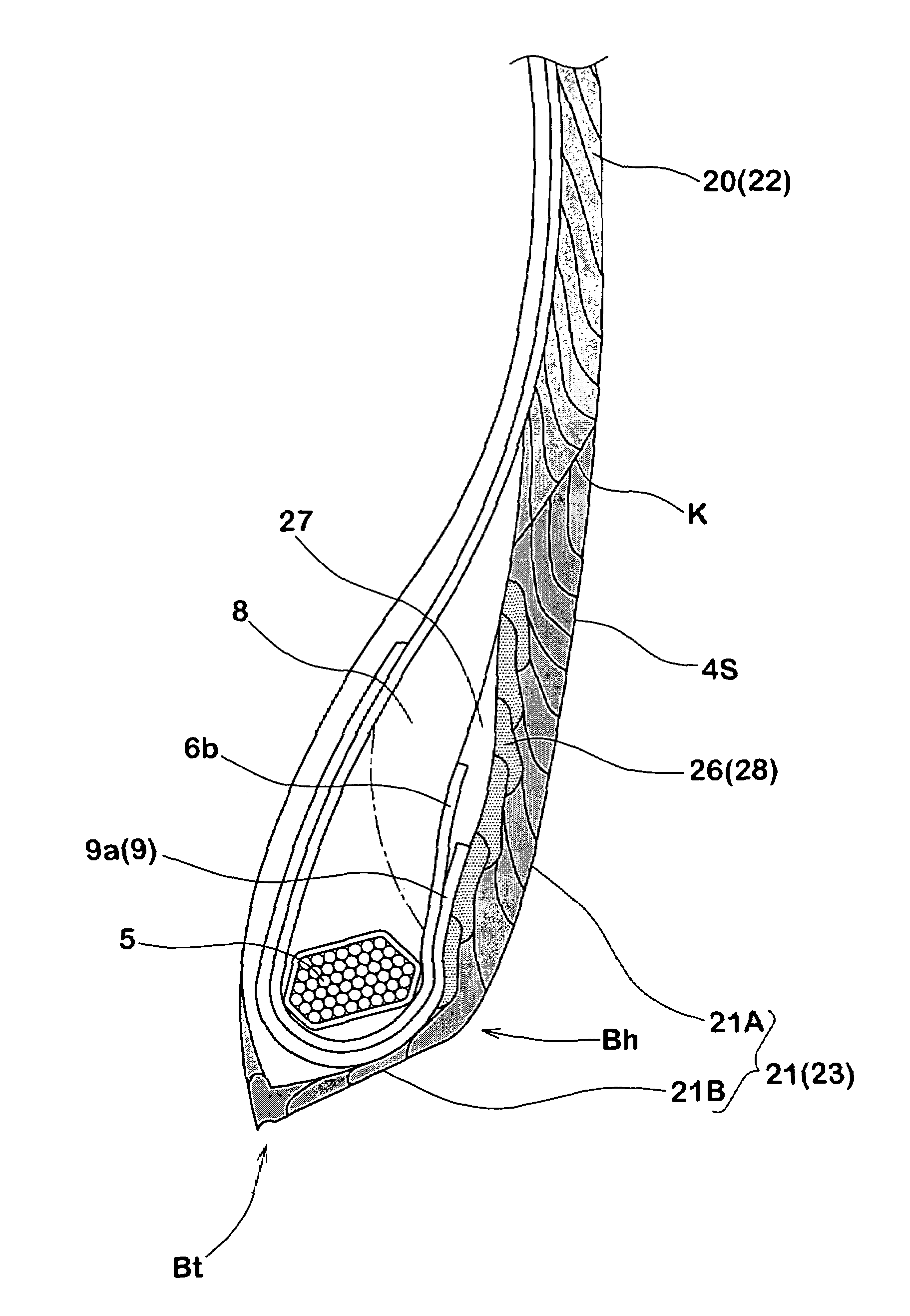
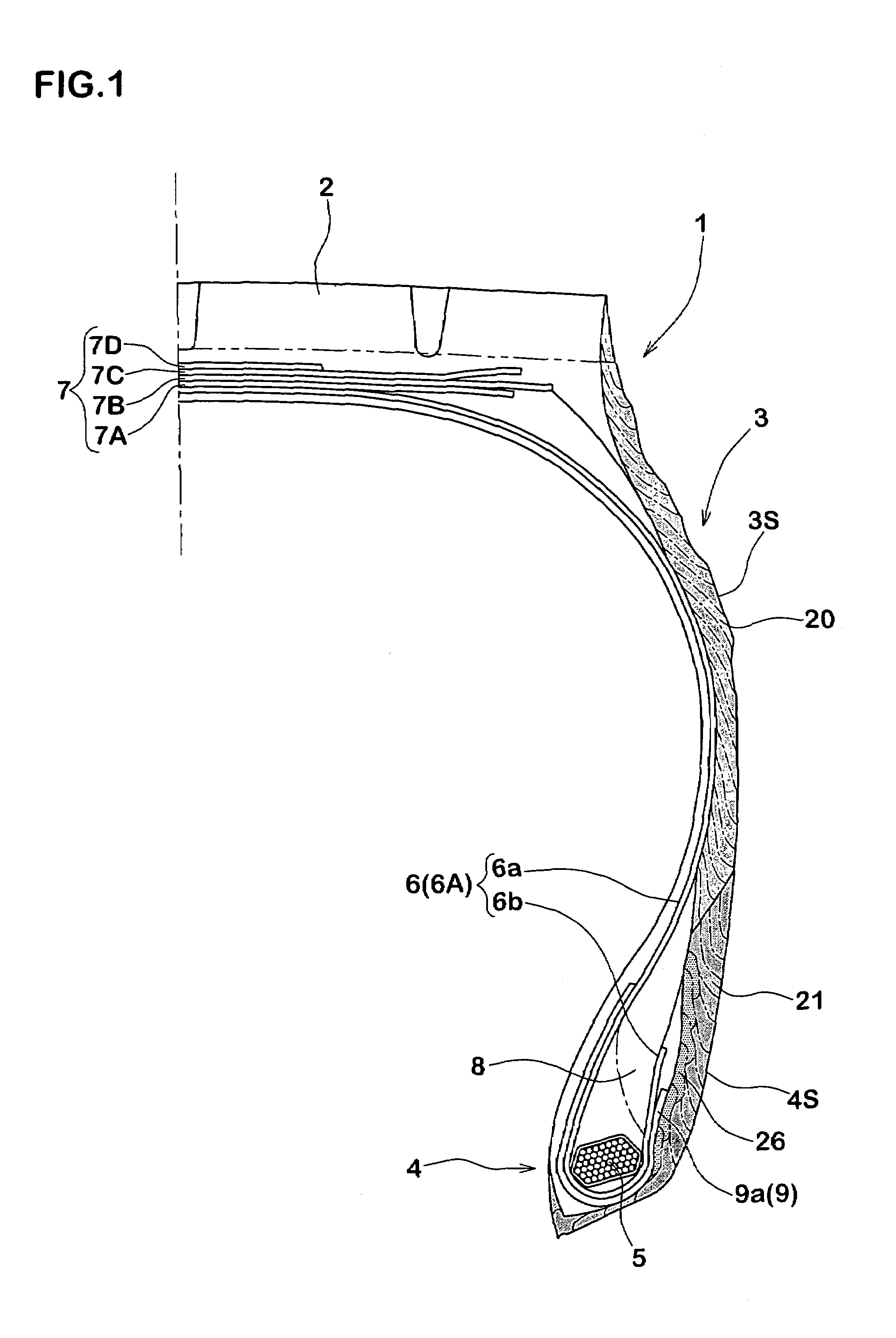
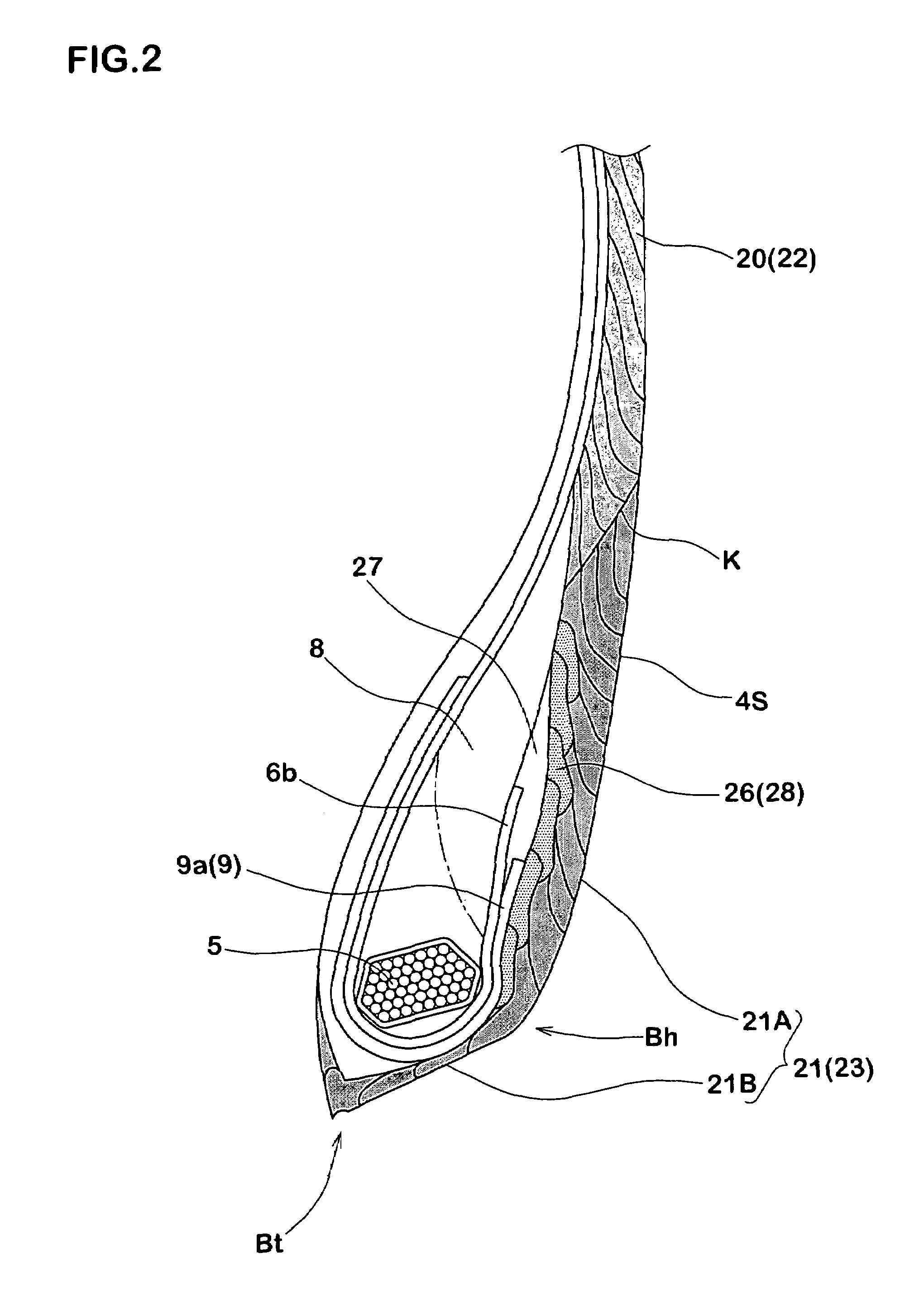
[0017]A description will be given of an embodiment in accordance with the present invention together with an illustrated embodiment. FIG. 1 is a cross sectional view exemplifying a case that a pneumatic tire in accordance with the present invention is constituted by a tire for a heavy load, and FIG. 2 is a cross sectional view showing a bead portion thereof in an enlarged view.

[0018]In FIG. 1, a pneumatic tire 1 is provided with at least a carcass 6 reaching a bead core 5 of a bead portion 4 from a tread portion 2 via a side wall portion 3, a side wall rubber 20 arranged in an outer side of the carcass 6 and forming an outer side surface 3S of the side wall portion 3, and a clinch rubber 21 connected to a lower end of the side wall rubber 20 and forming an outer side surface 4S of the bead portion 4, for preventing damage by rim displacement.

[0019]The carcass 6 is formed by one or more, one in the present embodiment, carcass ply 6A in which carcass cords are arranged, for example, a...


PUM

PropertyMeasurementUnit
angleaaaaaaaaaa
angleaaaaaaaaaa
angleaaaaaaaaaa

Abstract

A pneumatic tire comprises a carcass reaching a bead core of a bead portion from a tread portion via a side wall portion; a side wall rubber arranged in an outer side of said carcass and forming an outer side surface of said side wall portion; and a clinch rubber for preventing a rim displacement connected to a lower end of the side wall rubber and forming an outer side surface of said bead portion. The sidewall rubber and the clinch rubber are constituted by a strip wind body formed by winding and overlapping a side wall rubber strip and a clinch rubber strip in a circumferential direction and spirally, and the respective rubber strips are wound in the same direction from the bead portion side toward the tread portion side.

Description

BACKGROUND OF THE INVENTION[0001]The present invention relates to a pneumatic tire which can increase a winding working efficiency at a time of forming a side wall rubber and a clinch rubber in accordance with a strip wind method, and can inhibit a turbulence of a rubber strip, and a manufacturing method of the same.[0002]In the pneumatic tire, a conventional step at a time of forming the side wall rubber and the clinch rubber is shown in FIGS. 7(A) to 7(D).[0003]As shown in FIG. 7(A), in particular, a composite rubber body b comprising a side wall rubber b1 and a clinch rubber b2 which are integrally extruded from a rubber extruder is wound around a region on a former a and in both ends (FIG. 3) of a former a at one circle. Thereafter, as shown in FIG. 7(B), a carcass ply d is wound between the composite rubber bodies b and b at one circle while being bridged.[0004]Further, as shown in FIG. 7(B), a bead core e is set on an overlapping portion between the composite rubber body b and...

Claims


Application Information

Patent Timeline
Patent Type & Authority Patents(United States)
IPC IPC(8): B60C15/06B29D30/30B29D30/72B60C13/00
CPCB29D30/72B60C13/00B60C15/06Y10T152/10837Y10T152/10846Y10T152/10828B60C2015/0614
Inventor TAKAHASHI, MASANORIHAYASHI, NORIO
Owner SUMITOMO RUBBER IND LTD
Why Eureka
Try Eureka