Bias correcting phase compensating rate limiter

a phase compensating and bias correction technology, applied in the direction of electric controllers, navigation instruments, instruments, etc., can solve the problem that the actuator rate limit on the control surface that generates high transient loads is not suitable for use, and achieves high bandwidth control, high rate, and high bandwidth

Active Publication Date: 2009-12-01
THE BOEING CO
View PDF7 Cites 2 Cited by
  • Summary
  • Abstract
  • Description
  • Claims
  • Application Information

AI Technical Summary

Benefits of technology

[0004]In accordance with an embodiment of the present invention, a Bias Correcting Phase Compensating Rate Limiter is provided. The Bias Correcting Phase Compensating Rate Limiter defines a means of limiting actuator rate without introducing significant phase loss or biases between the actuator command and the response of the actuator for a significant class of systems encountered in aircraft flight control as well as other applications. The Bias Correcting Phase Compensating Rate Limiter is applicable to a class of systems wherein one has knowledge of a “trim” or “neutral” position that provides satisfactory performance for the actuator or signal that is to be rate limited when it is commanded in an oscillatory manner beyond its rate limit capability. This class of systems is relatively common in aviation and other applications requiring high bandwidth control, wherein an actuator capable of high rate but limited authority motion is supplemented by one or more secondary actuators with more limited rate capabilities but more control authority. Aircraft equipped with mechanical flight control systems and limited authority and rate stability augmentation actuators often employ this class of systems to provide high bandwidth command following and stabilization, avoid actuator authority saturation throughout the flight envelope, and provide docile and easily controllable responses to actuator failures. The class of systems addressed by this invention also encompasses aircraft equipped with redundant independent control surfaces with differing levels of transient structural load sensitivity to high rate control surface commands. Control surfaces that generate high transient loads would be actuator rate limited in this case, allowing them to be used for trim functions and low bandwidth control power enhancement.
[0007]In accordance with another embodiment of the present invention, a method to control movement of a device may include limiting a time rate of change of a device control signal. The method may also include substantially avoiding any phase loss in limiting the time rate of change of the device control signal. The method may further include substantially correcting for any bias in limiting the time rate of change of the device control signal without introducing phase loss between the input to and output from the device.
[0008]In accordance with another embodiment of the present invention, a method to control an aircraft may include controlling movement of an actuator. The method may also include limiting a time rate of change of an actuator control signal using a rate limiter. The method may also include substantially avoiding any phase loss in the rate limiter and substantially correcting for any bias between an input signal to the rate limiter and an output signal of the rate limiter.

Problems solved by technology

Control surfaces that generate high transient loads would be actuator rate limited in this case, allowing them to be used for trim functions and low bandwidth control power enhancement.

Method used


Image

  • Bias correcting phase compensating rate limiter
  • Bias correcting phase compensating rate limiter
  • Bias correcting phase compensating rate limiter

Examples


Embodiment Construction

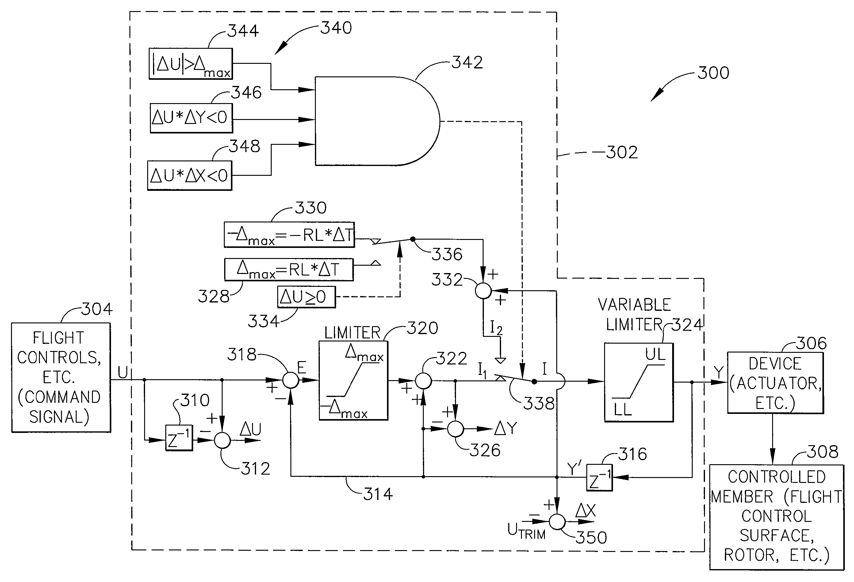
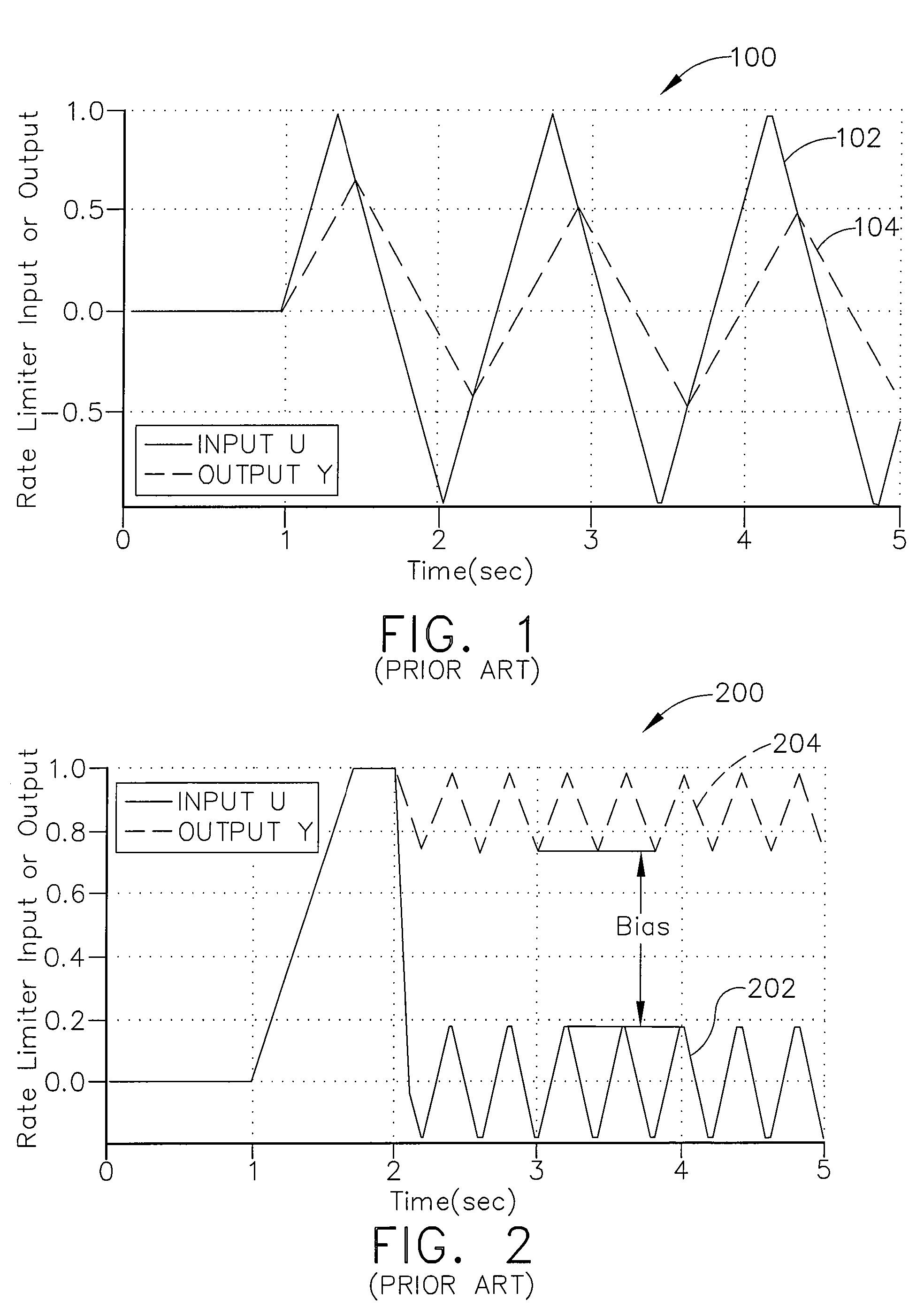
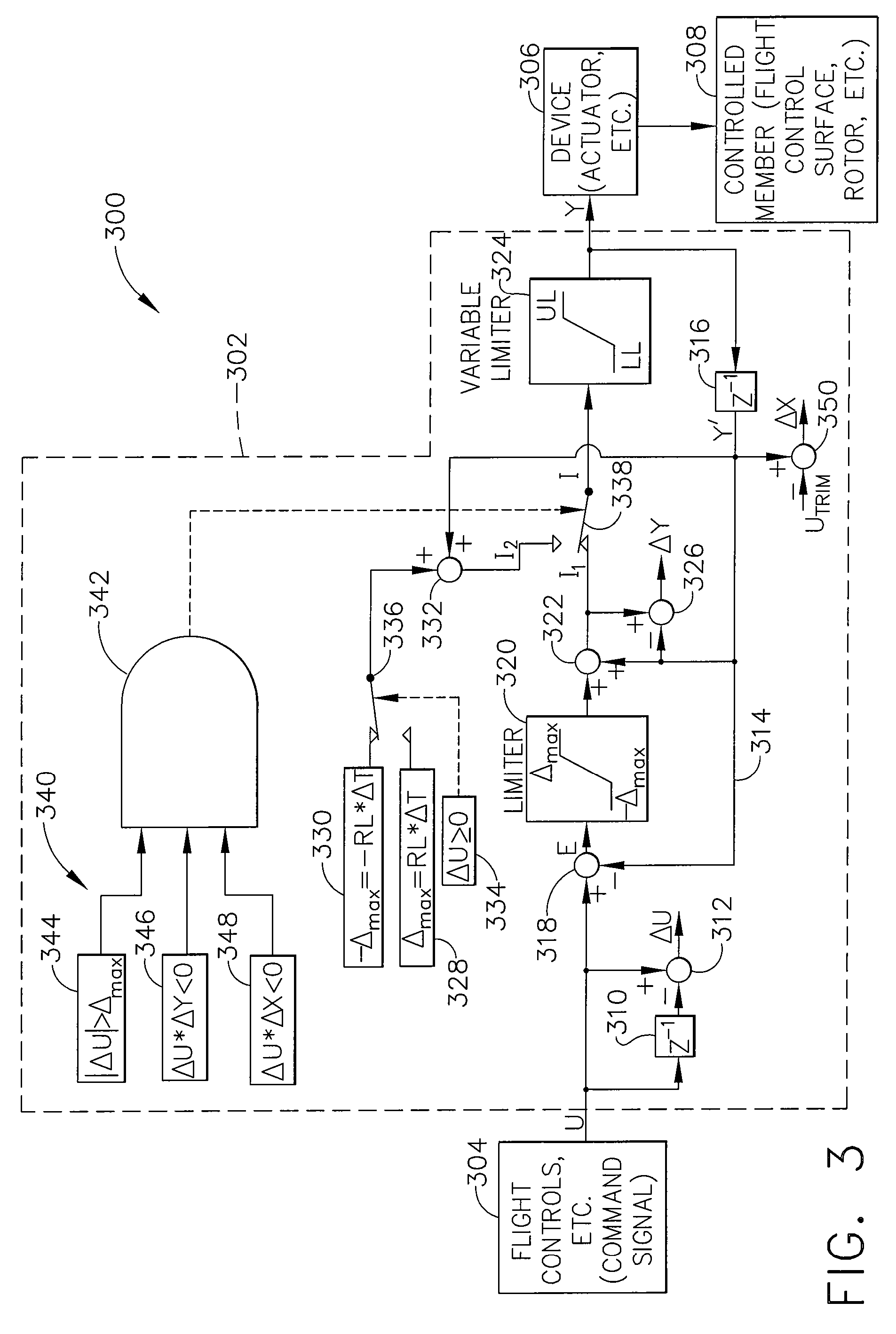
[0017]The following detailed description of embodiments refers to the accompanying drawings, which illustrate specific embodiments of the invention. Other embodiments having different structures and operations do not depart from the scope of the present invention.

[0018]As will be appreciated by one of skill in the art, the present invention may be embodied as a method, system, or computer program product. Accordingly, the present invention may take the form of an entirely hardware embodiment, an entirely software embodiment (including firmware, resident software, micro-code, etc.) or an embodiment combining software and hardware aspects that may all generally be referred to herein as a “circuit,”“module” or “system.” Furthermore, the present invention may take the form of a computer program product on a computer-usable storage medium having computer-usable program code embodied in the medium.

[0019]Any suitable computer usable or computer readable medium may be utilized. The computer...


PUM


Abstract

A bias correcting phase compensating rate limiter to control movement of a device may include a switching arrangement adapted to reverse a polarity of an error signal in response to a set of predetermined conditions that may include a commanded rate of movement of the device exceeding a rate limit capability of the device; a time rate of change of an input signal to the rate limiter being opposite in polarity to a difference between the input signal to the rate limiter and an output signal from the rate limiter; and a time rate of change of the input signal to the rate limiter being opposite in polarity to a difference between the output signal from the rate limiter and a signal corresponding to a pre-specified neutral or trim position of the device.

Description

BACKGROUND OF THE INVENTION[0001]The present invention relates to control systems for aircraft, aerospace vehicle or the like and more particularly to a bias correcting phase compensating rate limiter and method.[0002]Mechanical devices, such as actuators or the like, are typically used in fixed wing aircraft, helicopters, and tilt rotor aircraft to control movement of flight control members or surfaces, such as elevators, rudders, ailerons, engines, rotors, swashplates, blades and the like. These actuators are generally designed so that their maximum possible rate of displacement is low enough that actuator failures or inadvertent large and rapid pilot stick inputs cannot cause aircraft structural failure or loss of aircraft control. When it is impractical or inefficient to design actuators so that their maximum rate of motion is mechanically or hydraulically limited, the electronic circuitry or digital software that generates the driving input signals to the actuator is often desi...

Claims


Application Information

Patent Timeline
Patent Type & Authority Patents(United States)
IPC IPC(8): G01C23/00
CPCG05B19/416G05B11/36G05B13/0255G05D1/0607G05D1/0808
Inventor MILLER, DAVID G.LU, YI
Owner THE BOEING CO
Why Eureka
Try Eureka