Method and apparatus for remotely piloted landmine clearing platform with multiple sensing means
a technology of remote piloting and landmine clearing, applied in the direction of mine sweeping, offensive equipment, launching weapons, etc., can solve the problems of increasing the difficulty of detection and removal of singles, and reducing the effectiveness of current technology
Inactive Publication Date: 2009-12-01
KILKIS SAN
View PDF6 Cites 11 Cited by
- Summary
- Abstract
- Description
- Claims
- Application Information
AI Technical Summary
Benefits of technology
"The patent describes an innovative method and apparatus for detecting landmines, utilizing different detection techniques and a remotely operated miniature airborne vehicle carrying the detection modules. The detection apparatus can also be used for detecting underground utilities and possible explosive devices in railways, as well as household abnormalities. The technical effects of the invention include improved accuracy and efficiency in detecting landmines and other abnormalities, as well as reduced risk to human operators."
Problems solved by technology
Indeed, the cost to purchase and install a landmine is between $3 and $30 per device, while the cost to detect and remove a single landmine is between $300 and $1,000.
First, newer mines contain less metal and are often much smaller, thereby becoming more difficult to detect with existing and inexpensive technology.
The lack of metal in the landmine eliminates the efficacy of current, affordable detection devices, namely metal detectors.
Second, older landmines have often been in place for extended periods-often so long that any visual indication of its planting has disappeared and vegetation has grown over its surface.
The existence of vegetation over older landmines presents additional problems, including the fact that such vegetation often causes distortion of present detection techniques, since such techniques cannot be practiced immediately above the soil surface.
GPR may be limited by environmental conditions.
Unfortunately, low frequency signals provide poor resolution images in determining where such landmines may be.
These signatures are generally not sufficient to detect single landmines.
Drawbacks of known passive infrared detection techniques include the slight disparity in temperature that generally occurs through the day between a landmine and the ambient soil it is buried in.
Further, results may be greatly skewed by environmental conditions (i.e., a cool wind blowing over warm soil may disrupt readings).
Active infrared detectors also have drawbacks, including cost, size, and weight.
The main drawback of US detection devices is that US waves tend to greatly attenuate when the medium is air.
As it is often difficult and unsafe to have a US detection device in direct contact with the soil, the results of such devices may be somewhat unreliable, due to this distance.
There are further drawbacks associated with each of the discussed detection devices.
Generally, their costs are prohibitive, especially to the under-developed countries that most have the need for them.
Further, the majority of devices require direct human operation, thereby placing lives in jeopardy.
Method used
View moreImage
Smart ImageViewing Examples
Examples
second embodiment
[0046]In the present invention, the landmine detection techniques may be utilized to determine the location of underground utilities, possible explosive devices located in railways, leaks in pipes embedded within a household, and / or electrical shorts in wiring embedded within a household.
third embodiment
[0047]In the present invention, the landmine detection and neutralization techniques may be utilized over water or ice like a sea, pond, river or marshland.
Login to View More PUM
 Abstract
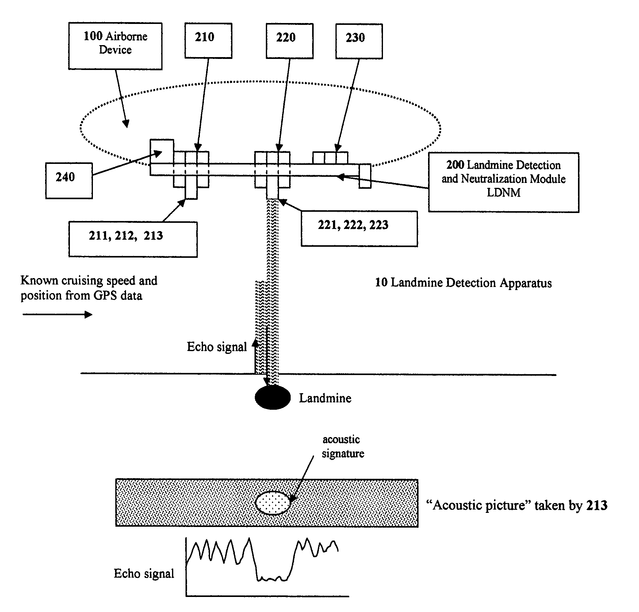
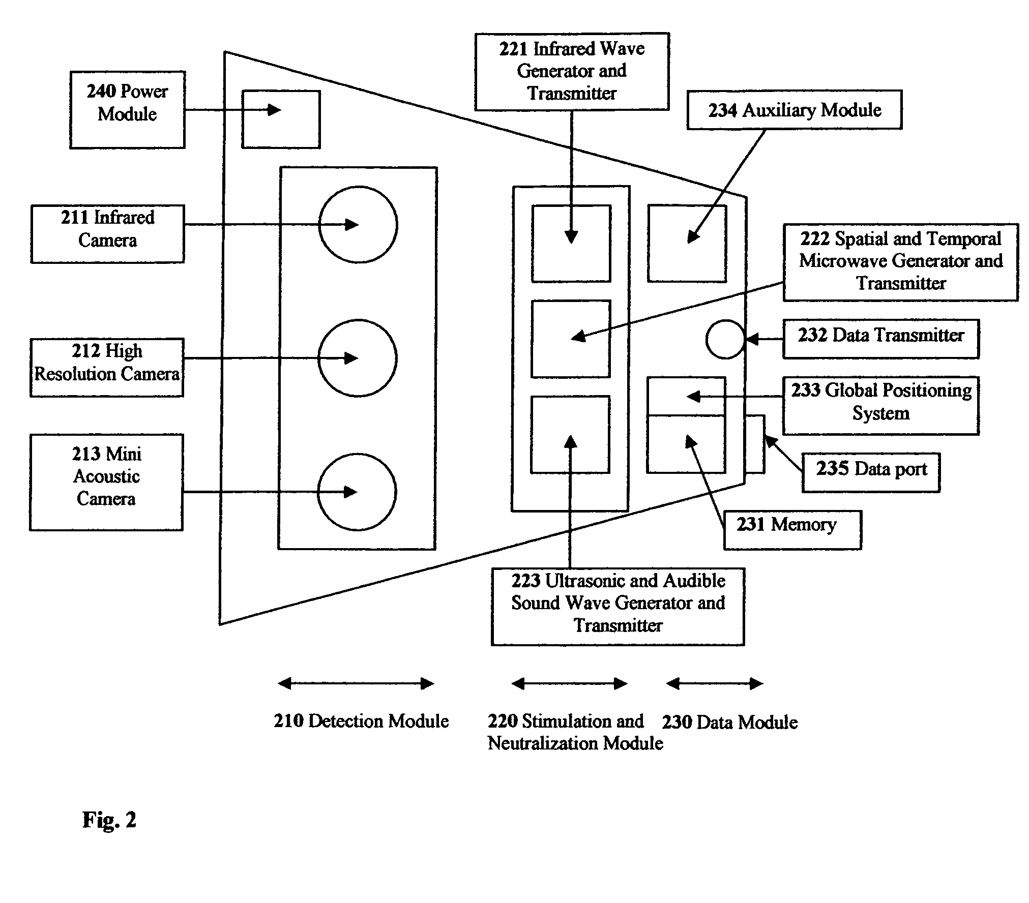
A landmine detection and neutralization apparatus and method is disclosed. The apparatus to determine the location of landmines, comprises at least two detection modules utilizing different infrared, sound, and / or optical detection and a remotely operated miniature airborne vehicle, that may carry the detection modules at an optimum altitude over a surface that may contain landmines. The neutralization device may be a microwave and / or infrared wave generator. The method for determining the location of landmines comprises using at least two different landmine detection techniques where the techniques are infrared, sound, and optical detection, operating the detection techniques in a close proximity to a surface that may contain landmines and maintaining this close proximity by operating a remotely operated miniature airborne vehicle. Neutralization may be achieved by directing microwaves or infrared waves at detected landmines.
Description
CROSS-REFERENCE TO RELATED APPLICATIONS[0001]The present application relates to, and claims the priority of, U.S. Provisional Patent Application Ser. No. 60 / 571,912, filed May 18, 2004, which is entitled “Thermal and Infrared Camera Combination to Detect Landmines from a Remotely Piloted Mini Helicopter.”FIELD OF THE INVENTION[0002]The present invention is generally directed to an apparatus and method for detecting and potentially neutralizing landmines. Specifically, the present invention is directed to an apparatus and method for detecting landmines which may use multiple sensors, thermal, acoustic, and / or electromagnetic sensors.BACKGROUND OF THE INVENTION[0003]Current statistics state that more than 26,000 people are killed or wounded by landmines every year. Approximately one death or injury occurs every twenty minutes. Presently, it is estimated that there are more than 100 million antipersonnel or antitank mines in more then seventy countries. Already, 11 million mines have b...
Claims
Login to View More Application Information
Patent Timeline
 Patent Type & Authority Patents(United States)
IPC IPC(8): B63G7/08B63G7/06F41F5/00F41H11/12
CPCF41H11/12
Inventor KILKIS, SAN
Owner KILKIS SAN
Features
- R&D
- Intellectual Property
- Life Sciences
- Materials
- Tech Scout
- Unparalleled Data Quality
- Higher Quality Content
- 60% Fewer Hallucinations
Learn More Browse by: Latest US Patents, China's latest patents, Technical Efficacy Thesaurus, Application Domain, Technology Topic, Popular Technical Reports.
© 2025 PatSnap. All rights reserved.Legal|Privacy policy|Modern Slavery Act Transparency Statement|Sitemap|About US| Contact US: help@patsnap.com


