Moire reducing optical substrates with irregular prism structures

a technology of prism structure and optical substrate, applied in the direction of optical elements, lighting and heating apparatus, instruments, etc., can solve the problems of significant trimming, increased production costs, appearance of moiré patterns, etc., and achieve the effect of reducing moiré effects and enhancing luminance or brightness

Active Publication Date: 2009-11-17
UBRIGHT OPTRONICS CORP
View PDF48 Cites 58 Cited by
  • Summary
  • Abstract
  • Description
  • Claims
  • Application Information

AI Technical Summary

Benefits of technology

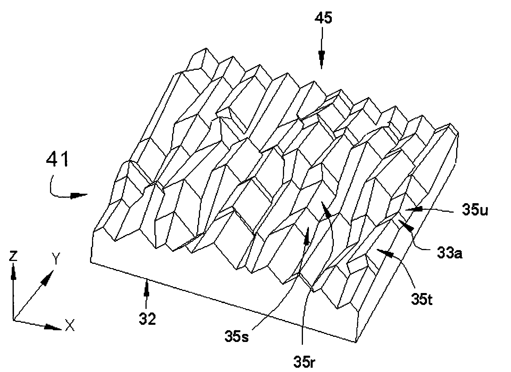
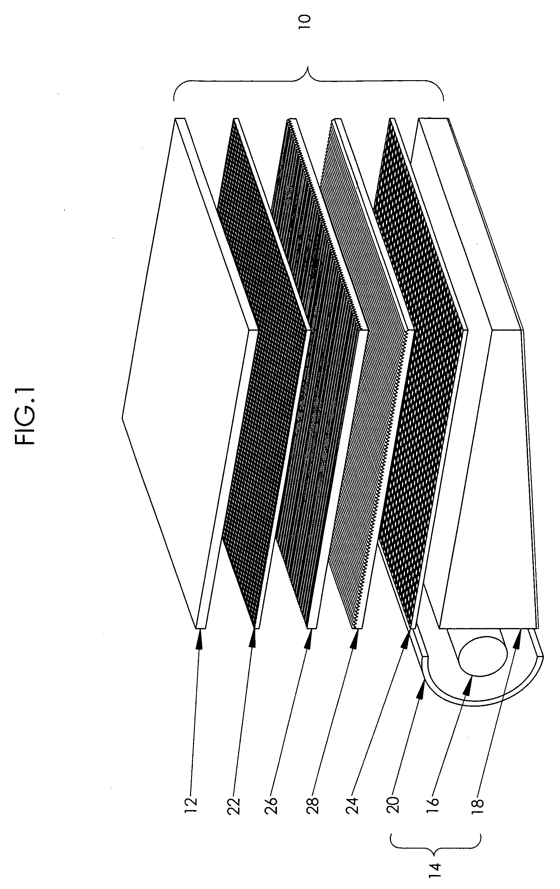
[0013]The present invention is directed to an optical substrate that possesses a structured surface that enhances luminance or brightness and reduces moiré effect in a single substrate. In one aspect of the present invention, the optical substrate is in the form of a film, sheet, plate, and the like, which may be flexible or rigid, having a three-dimensionally varying, structured light output surface that comprises an irregular prism structure, and a non-structured, smooth, planar, light input surface.

Problems solved by technology

An undesirable effect arising from using two brightness enhancement films in a flat panel display is the appearance of moiré patterns caused by the interference of the two periodic patterns of the prismatic structures on the surfaces of the two brightness enhancement films.
However, due to conventional manufacturing processes for brightness enhancement films, significant trimming is required to obtain a rectangular shaped brightness enhancement film for use with a rectangular flat panel display, such that the prismatic structures are rotated at an angle relative to the pixel array in the LC module.
This significantly increases costs of production.
This disclosure proposes a rather complicated method to derive the surface structure for the optical substrate.
Further, it is doubtful of the level of brightness enhancement that can be achieved with the disclosed structure, as compared to prism films.

Method used


Image

  • Moire reducing optical substrates with irregular prism structures
  • Moire reducing optical substrates with irregular prism structures
  • Moire reducing optical substrates with irregular prism structures

Examples


Embodiment Construction

[0037]The present description is of the best presently contemplated mode of carrying out the invention. This invention has been described herein in reference to various embodiments and drawings. This description is made for the purpose of illustrating the general principles of the invention and should not be taken in a limiting sense. It will be appreciated by those skilled in the art that variations and improvements may be accomplished in view of these teachings without deviating from the scope and spirit of the invention. The scope of the invention is best determined by reference to the appended claims.

[0038]The present invention is directed to an optical substrate that possesses a structured surface that enhances brightness and reduces moiré effect. In one aspect of the present invention, the optical substrate is in the form of a film, sheet, plate, and the like, which may be flexible or rigid, having a three-dimensionally varying, structured light output surface that comprises a...


PUM

PropertyMeasurementUnit
angleaaaaaaaaaa
correlation lengthaaaaaaaaaa
vertex angleaaaaaaaaaa

Abstract

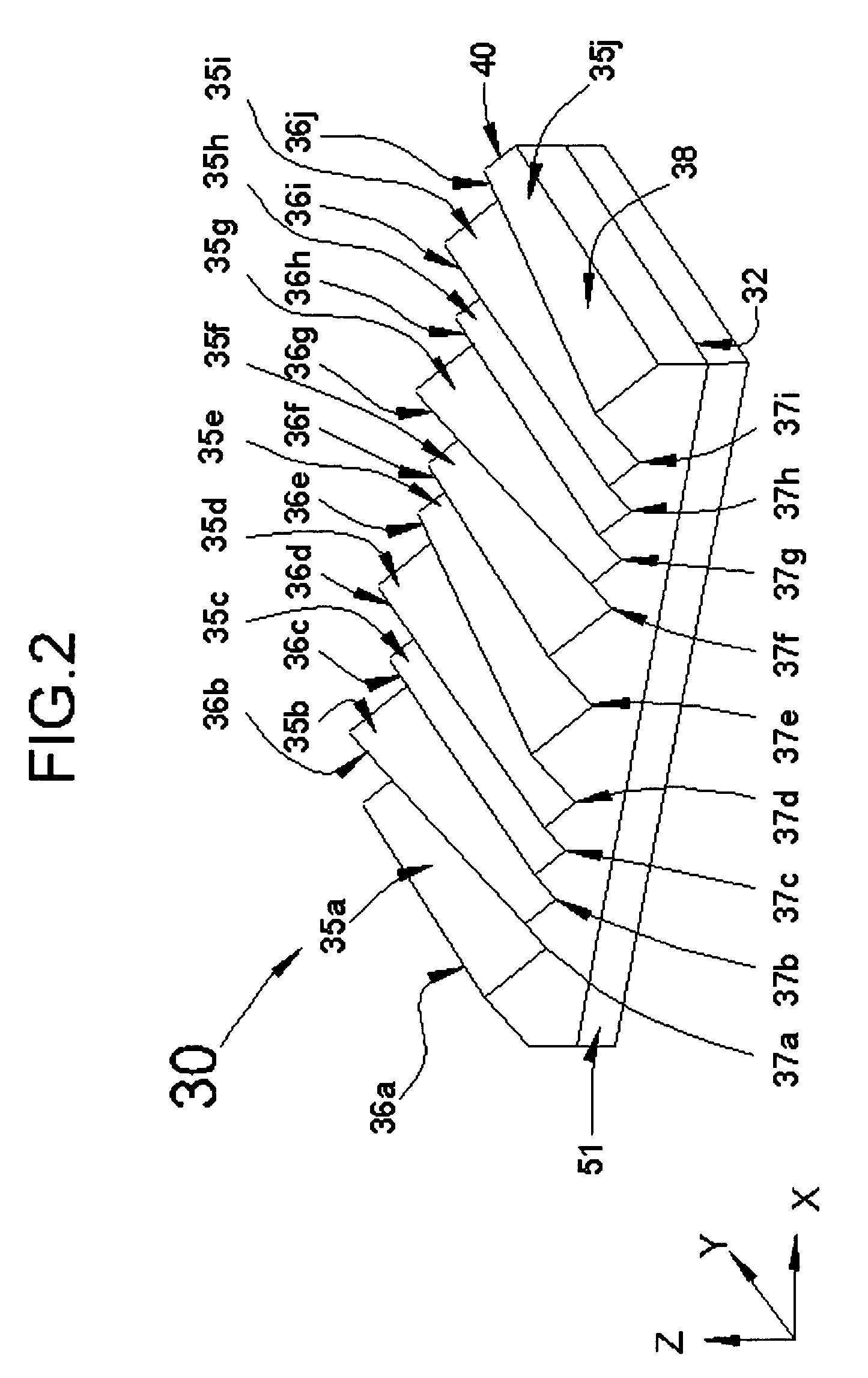
An optical substrate having a structured surface that enhances brightness and reduces moiré effect. The optical substrate has a three-dimensionally varying, structured light output surface that comprises an irregular prismatic structure. The irregular prismatic structure may be viewed as comprising longitudinal prism blocks or rows thereof, arranged laterally defining peaks and valleys. Adjacent peaks, adjacent valleys, and / or adjacent peak and valley may be parallel or non-parallel, in an orderly, semi-orderly, random, or quasi-random manner. The lateral adjacent peaks, adjacent valleys, and / or adjacent peak and valley are not parallel. The adjacent irregular prism blocks may be irregular longitudinal sections having the same length, or random or quasi-random irregular sections having different lengths. The facets of each prism block may be flat, or curved (convexly and / or concavely).

Description

[0001]This application claims the priority of U.S. Provisional Application No. 60 / 689,650, filed Jun. 9, 2005. This document is fully incorporated by reference as if fully set forth herein.[0002]The publications noted in the disclosure herein are each fully incorporated by reference, as if fully set forth in its entirety herein.BACKGROUND OF THE INVENTION[0003]1. Field of the Invention[0004]The present invention relates to optical substrates having a structured surface, particularly to optical substrates for brightness enhancement, and more particularly to brightness enhancement substrates for use in flat panel displays having a planar light source.[0005]2. Description of Related Art[0006]Flat panel display technology is commonly used in television displays, computer displays, and handheld electronics (e.g., cellular phones, personal digital assistants (PDAs), etc.). Liquid crystal display (LCD) is a type of flat panel display, which deploys a liquid crystal (LC) module having an ar...

Claims


Application Information

Patent Timeline
Patent Type & Authority Patents(United States)
IPC IPC(8): F21V5/02
CPCG02B5/0221G02B5/045G02B6/0053G02B27/126G02B27/1073G02F1/133606G02F1/133504F21V5/005G02B5/04G02B6/00G02F1/1335G02B6/0061G02F1/133507
Inventor WANG, KONG-HUALIN, CRAIGKO, DANIEL YAW-CHUNG
Owner UBRIGHT OPTRONICS CORP
Why Eureka
Try Eureka