Light directing film

a technology of optical substrates and light directing films, applied in the field of optical substrates with brightness enhancement, can solve the problems of significant trimming, increased production costs, and moiré pattern appearance, and achieve the effects of reducing the likelihood of wet-out, enhancing brightness, and inhibiting the occurrence of undesired optical coupling

Active Publication Date: 2015-09-17
UBRIGHT OPTRONICS CORP
View PDF9 Cites 4 Cited by
  • Summary
  • Abstract
  • Description
  • Claims
  • Application Information

AI Technical Summary

Benefits of technology

[0020]When the second optical sheet (e.g., light directing film) is placed close to the first structured major surface of the light directing film (i.e. the first optical sheet), the ridges (or peaks, apexes) of the taller prism elements having the maximum of the first height of the first ridge of the first prism elements limit the proximity of the second optical sheet to the first structured major surface of the light directing film, thereby reducing the likelihood of wet-out. The height difference between the taller prism elements and shorter prism elements significantly inhibits the occurrence of undesired optical coupling in the zone of shorter prism elements....

Problems solved by technology

An undesirable effect arising from using two brightness enhancement films in a flat panel display is the appearance of moiré patterns caused by the interference of the two periodic patterns of the prismatic structures on the surfaces of the two brightness enhancement films.
However, due to conventional manufacturing processes for brightness enhancement films, significant trimming is required to obtain a rectangular shaped brightness enhancement film for use with a rectangular flat panel display, such that the prismatic str...

Method used


Image

  • Light directing film
  • Light directing film
  • Light directing film

Examples


Embodiment Construction

[0049]The present description is of the best presently contemplated mode of carrying out the invention. This invention has been described herein in reference to various embodiments and drawings. This description is made for the purpose of illustrating the general principles of the invention and should not be taken in a limiting sense. It will be appreciated by those skilled in the art that variations and improvements may be accomplished in view of these teachings without deviating from the scope and spirit of the invention. The scope of the invention is best determined by reference to the appended claims.

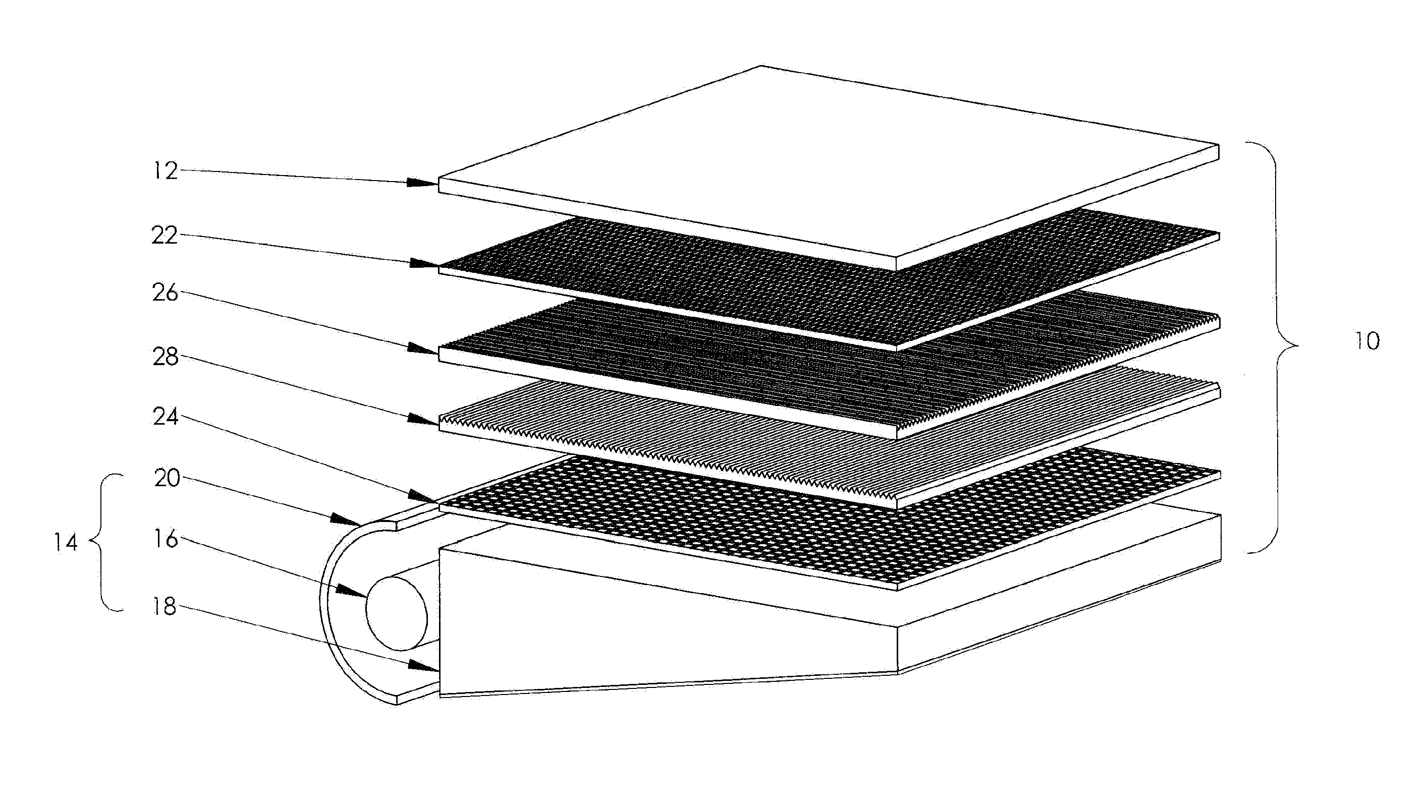
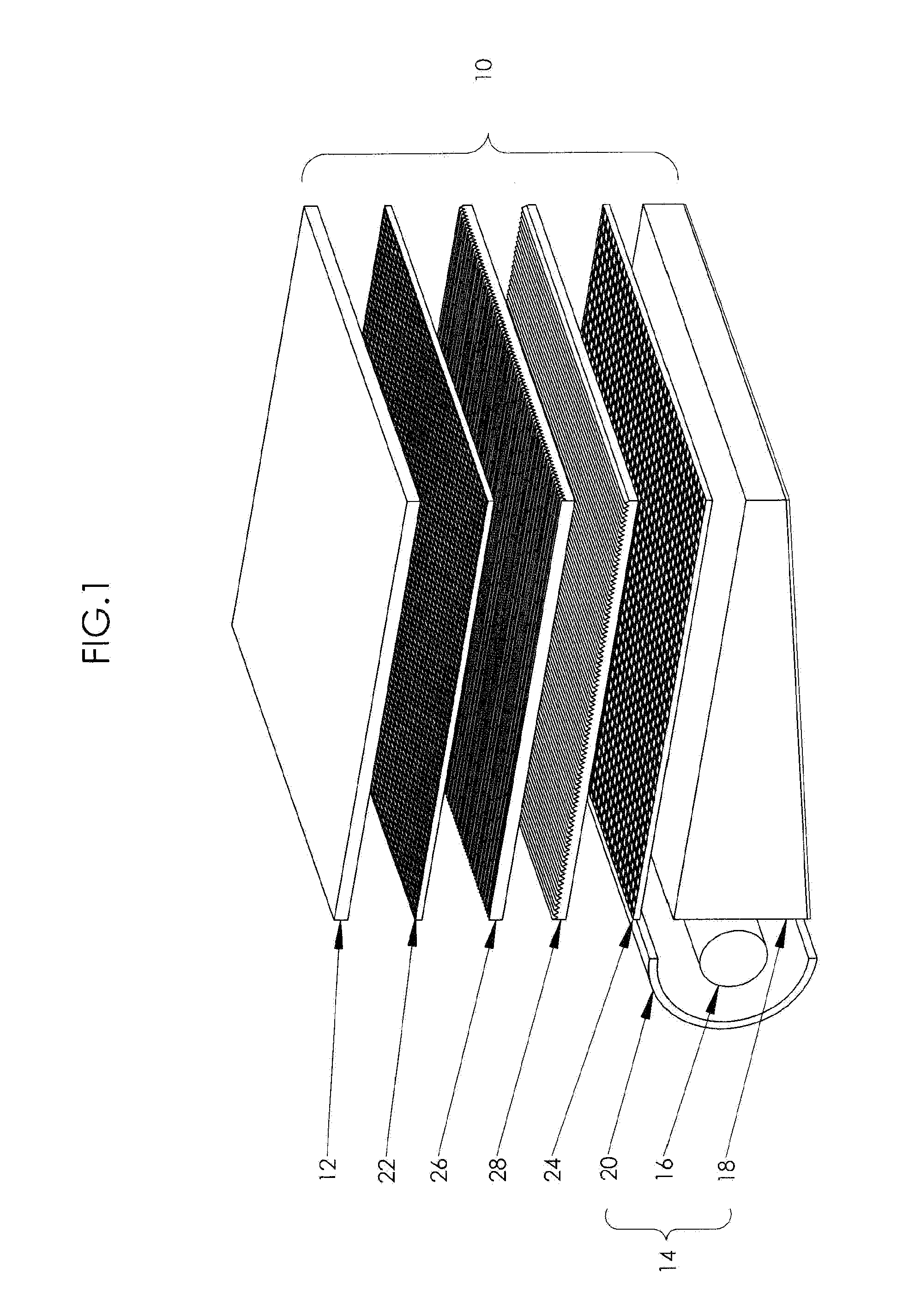
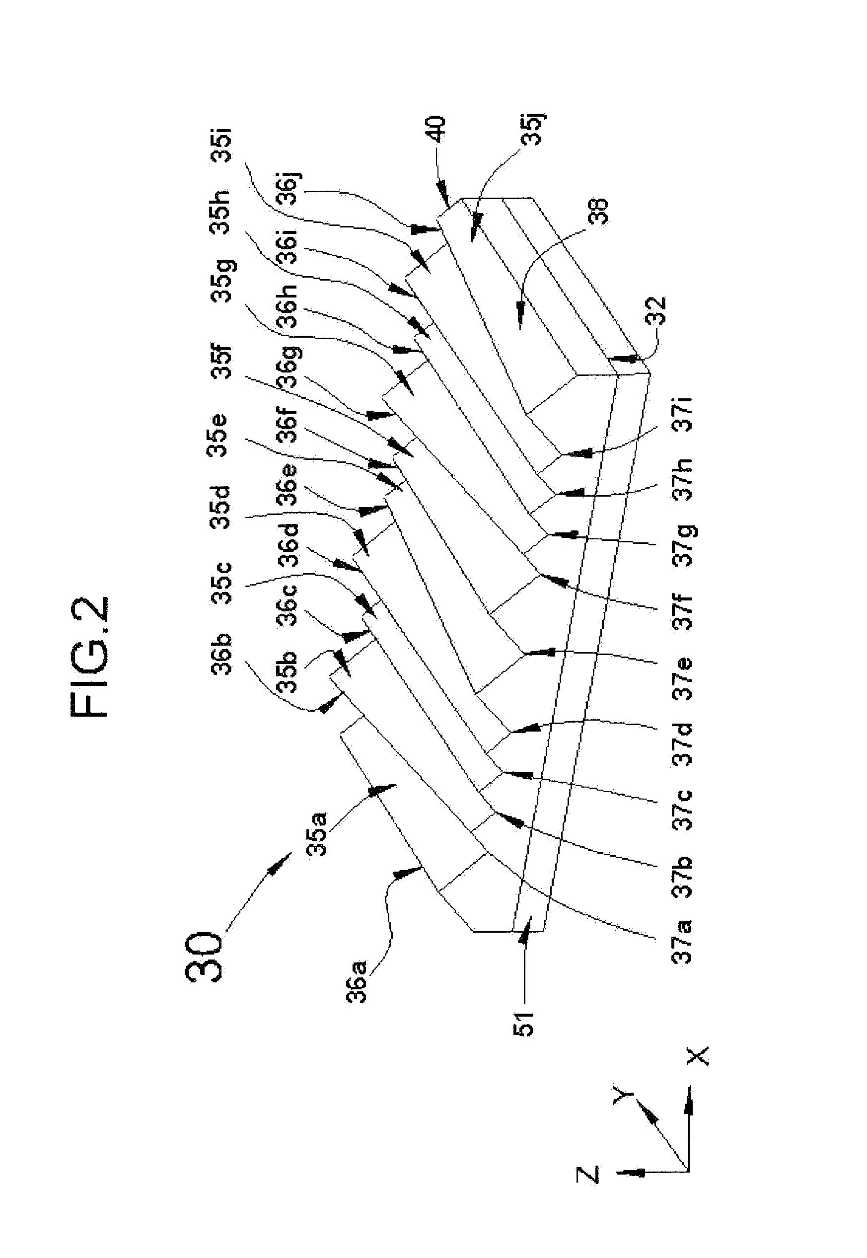
[0050]The present invention is directed to an optical substrate that possesses a structured surface that enhances brightness and reduces moiré effect. In one aspect of the present invention, the optical substrate is in the form of a film, sheet, plate, and the like, which may be flexible or rigid, having a three-dimensionally varying, structured light output surface that comprises a...


PUM


Abstract

The present invention discloses a light directing film comprising a first structured major surface, a second major surface opposite to the first structured major surface and a reference plane between the first structured major surface and the second major surface, wherein the reference plane is substantially perpendicular to the thickness direction of the light directing film, wherein the first structured major surface comprises a first prism element and a second prism element extending substantially in a first direction, wherein a first ridge of the first prism element has a first height relative to the reference plane and a second ridge of the second prism element has a second height relative to the reference plane, wherein the first height of the first ridge of the first prism element varies along the first direction. Preferably, the maximum of the first height is larger than the maximum of the second height.

Description

CROSS-REFERENCE TO RELATED APPLICATIONS[0001]This application is a continuation-in-part of U.S. patent application Ser. No. 14 / 010,478 filed on Aug. 26, 2013, which is a continuation of U.S. patent application Ser. No. 12 / 590,855 filed on Nov. 12, 2009, now U.S. Pat. No. 8,517,573, which is a continuation of U.S. patent application Ser. No. 11 / 450,145 filed on Jun. 9, 2006, now U.S. Pat. No. 7,618,164, which claims priority of U.S. provisional application Ser. No. 60 / 689,650 filed on Jun. 9, 2005. All of these applications are incorporated by referenced herein in their entirety.BACKGROUND OF THE INVENTION[0002]1. Field of the Invention[0003]The present invention relates to optical substrates having a structured surface, particularly to optical substrates for brightness enhancement, and more particularly to brightness enhancement substrates for use in flat panel displays having a planar light source.[0004]2. Description of Related Art[0005]Flat panel display technology is commonly us...

Claims


Application Information

Patent Timeline
IPC IPC(8): G02B27/12
CPCG02B27/126G02B5/0221G02B5/0231G02B5/0278G02B5/045G02B6/0053G02F1/133606
Inventor WANG, KONG-HUAYANG, CHING-ANPAN, HAN-TSUNG
Owner UBRIGHT OPTRONICS CORP
Why Eureka
Try Eureka