
Accelerometer

a technology of accelerometer and accelerometer body, which is applied in the direction of acceleration measurement, measurement devices, instruments, etc., can solve the problems of reducing the sensitivity of the accelerometer, affecting the accuracy of the accelerometer, so as to facilitate the increase of the rotor (moving part), reduce the thermodynamical noise, and facilitate the effect of increasing the capacitive sensitivity

Active Publication Date: 2009-11-17
PHYSICAL LOGIC LTD
View PDF18 Cites 121 Cited by
  • Summary
  • Abstract
  • Description
  • Claims
  • Application Information

AI Technical Summary

Benefits of technology

"The present invention is about a MEMS device that uses capacitive plates to detect movement. The device includes a proof mass frame and a substrate with two arrays of capacitive plates. The capacitive plates are arranged in a way that their movement causes a change in the overlap area between stationary and moving electrodes. The invention also includes a differential circuit for eliminating noise and a method for fabricating a MEMS device with electrical isolation between each of the arrays connected to opposite poles of a power supply. The invention also involves processing the SOI wafer from two sides to increase the mass of the rotor and decrease thermo-dynamical noise. The technical effects of the invention include improved sensitivity and reduced noise in detecting movement."

Problems solved by technology

Such devices have inherent limitations on the minimum size, detection limit, sensitivity and the like, largely due to the means used for detecting the deflection of the proof mass.
In particular, as attempts have been made to miniaturize accelerometer devices for diverse applications using the technology prior to this applicants invention important aspects of performance have been compromised.
In particular, it has been difficult for the prior art devices to achieve both a low noise floor and the required capacitive sensitivity.

Method used


Image

  • Accelerometer
  • Accelerometer
  • Accelerometer

Examples


Embodiment Construction

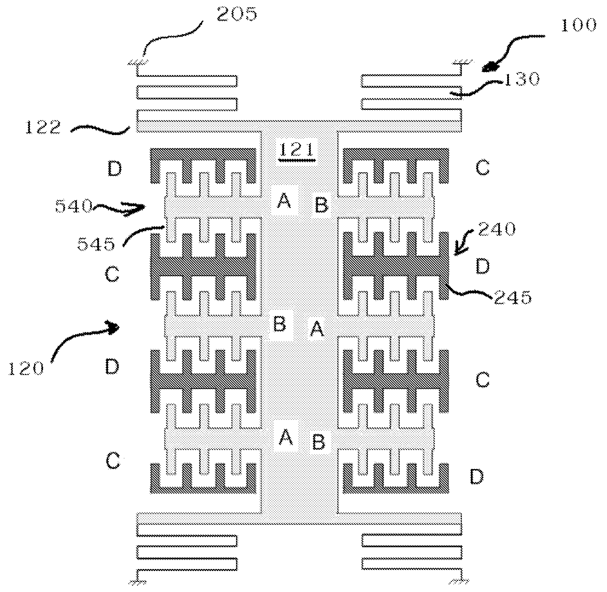
[0039]Referring to FIGS. 1 through 12, wherein like reference numerals refer to like components in the various views, there is illustrated therein a new and improved accelerometer, generally denominated 100 herein.

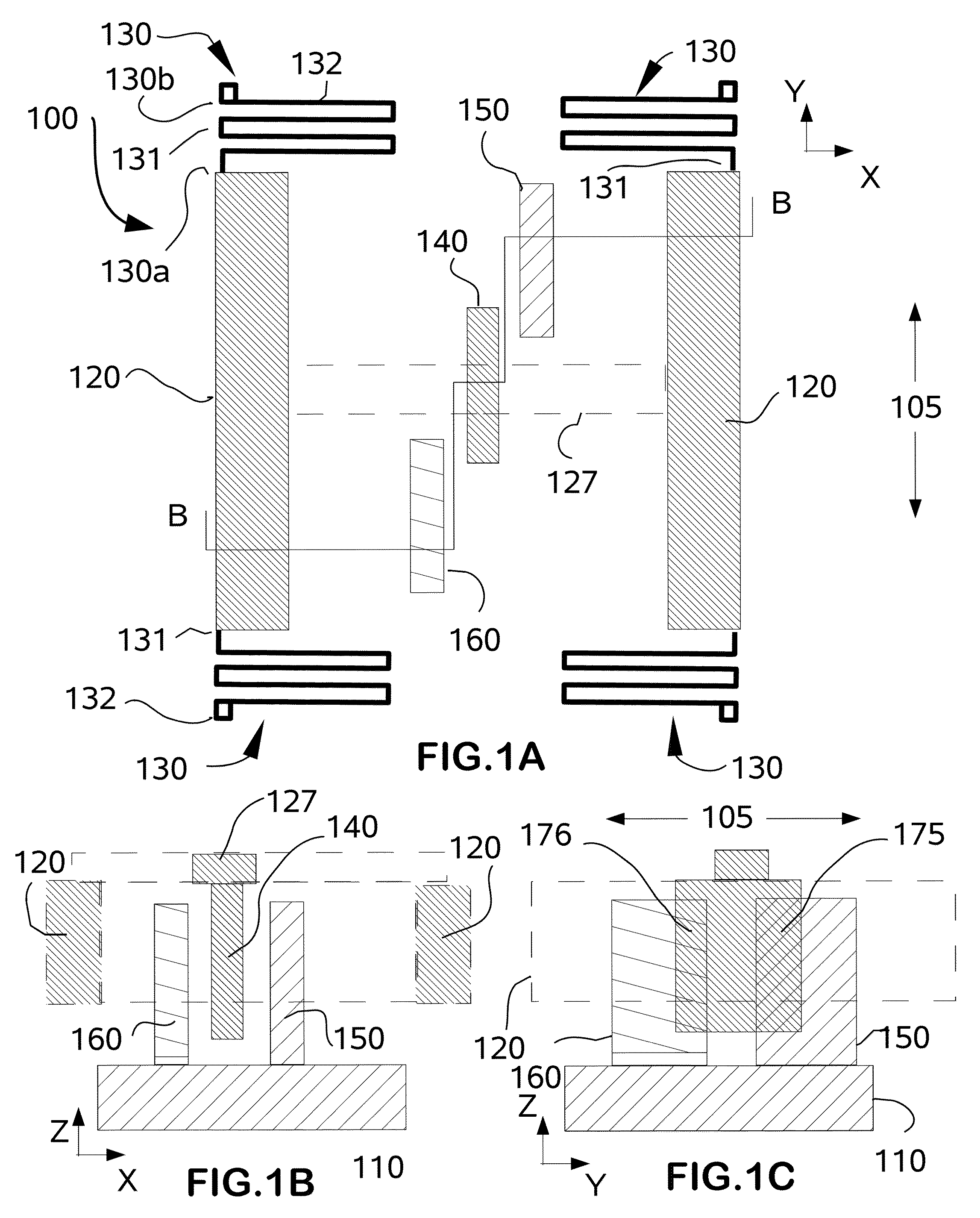
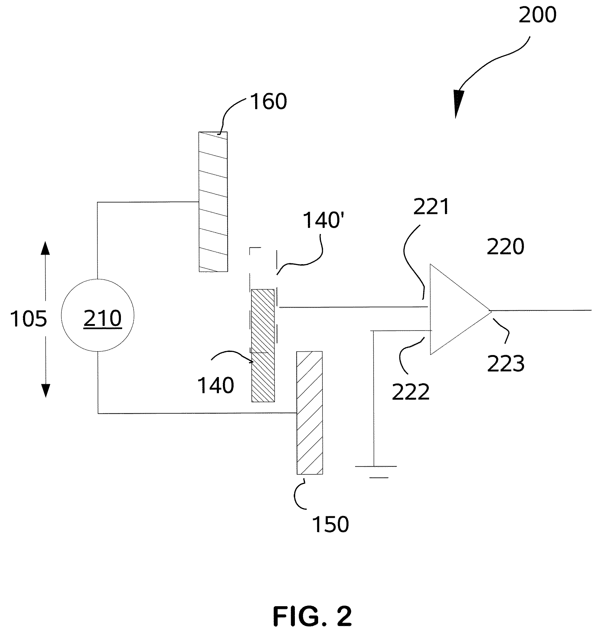
[0040]In accordance with the present invention, the operative principles will first be illustrated with reference to FIG. 1, which illustrates a portion of the operative accelerometer 100 that includes a substrate 110 which supports a pair of capacitive plates 160 and 150 that extend upward therefrom. As will be illustrated in other embodiments, the capacitive plates can be connected to the substrate in alternative configurations, provided that in general they are disposed orthogonal to the plane of the substrate. Generally, capacitive plates 160 and 150 are electrically isolated from each other, as shown in the circuit diagram 200 of FIG. 2. A third capacitive plate 140 is suspended above the substrate 110 in a parallel orientation between capacitive plates 150 and 160 by...


PUM


Abstract

An accelerometer is fabricated as a MEMS device and includes an array of capacitive electrode plates mechanically coupled to a common proof mass.The proof mass is constrained to move or vibrate in the plane parallel to the first array of plates. The capacitance between the first array of plates is measured with respect to additional arrays of capacitive plates inter-digitated in a comb like pattern.

Description

CROSS REFERENCE TO RELATED APPLICATIONS[0001]The present application claims priority to the U.S. Provisional Patent Application filed on Feb. 21, 2006, entitled “Accelerometer” and having Ser. No. 60 / 775,530.BACKGROUND OF INVENTION[0002]The present invention relates to micro-mechanical electrical systems (MEMS) type device for measuring vibration and movement, and more particularly to a MEMS accelerometer.[0003]MEMS type devices for use as sensors and accelerometers are well known. Such devices are generally fabricated on a silicon or related planar substrate by semi-conductor manufacturing type methods, such as the use of photoresists, masks and various etching processes to fabricate a proximity sensor that includes a suspended proof mass member and means to measure the deflection of the proof mass suspending means. Such devices have inherent limitations on the minimum size, detection limit, sensitivity and the like, largely due to the means used for detecting the deflection of the...

Claims


Application Information

Patent Timeline
Patent Type & Authority Patents(United States)
IPC IPC(8): G01P15/125
CPCG01P15/125G01P2015/0814
Inventor AXELROD, NOELOFEK, ERAN
Owner PHYSICAL LOGIC LTD
Learn More