Fastener and ornament including the fastener
a technology of fasteners and ornaments, applied in the field of fasteners, can solve the problems of easy expansion of rubber-like elastic parts, loss of pinching force of fasteners, and inability to use properly, and achieve the effect of restricting the lowering of the pinching capability of a pinched portion and improving durability
- Summary
- Abstract
- Description
- Claims
- Application Information
AI Technical Summary
Benefits of technology
Problems solved by technology
Method used
Image
Examples
first embodiment
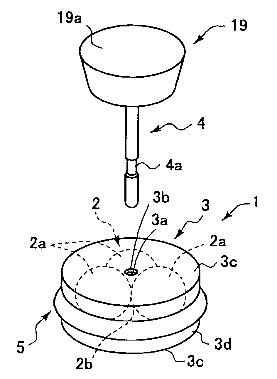
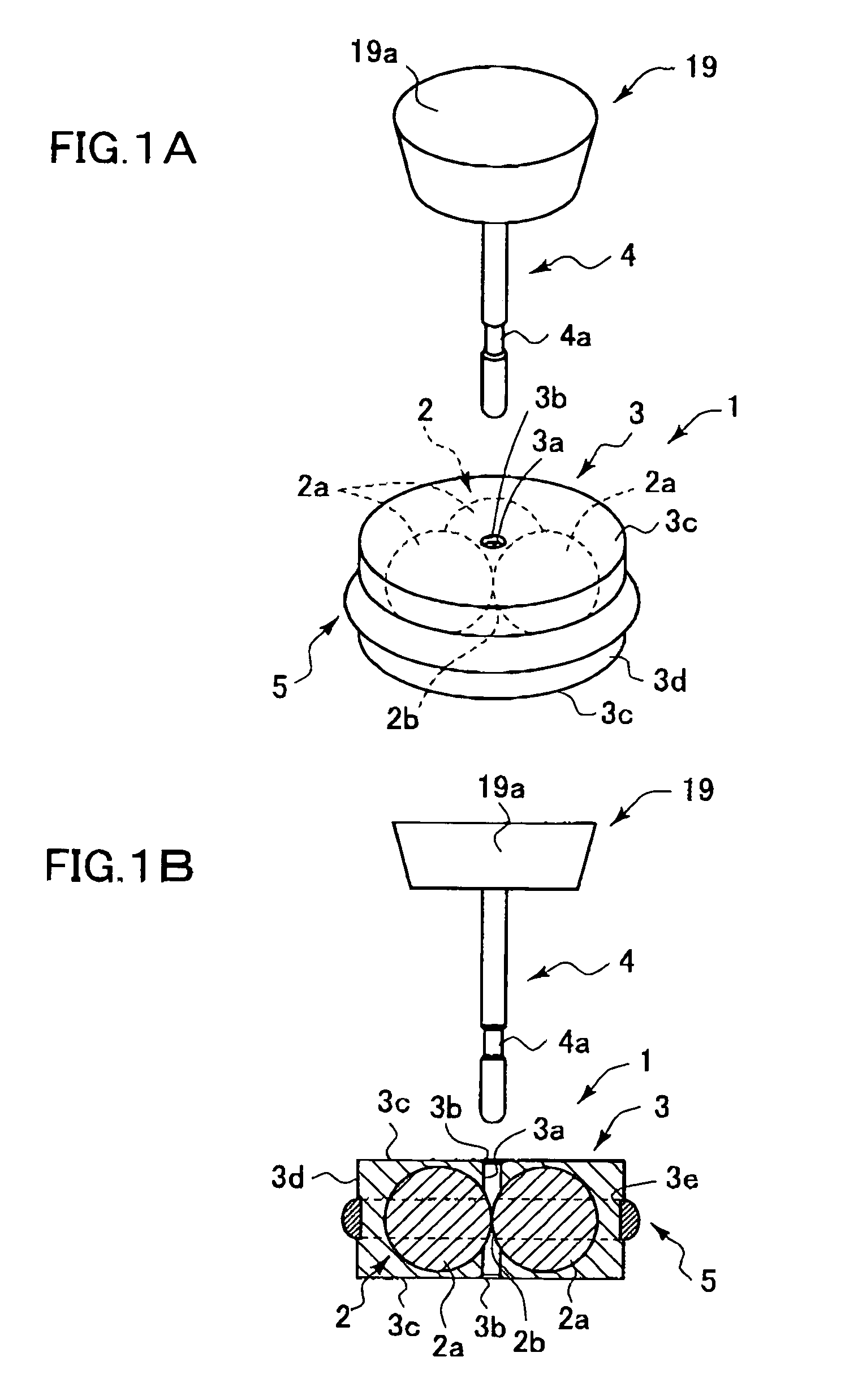
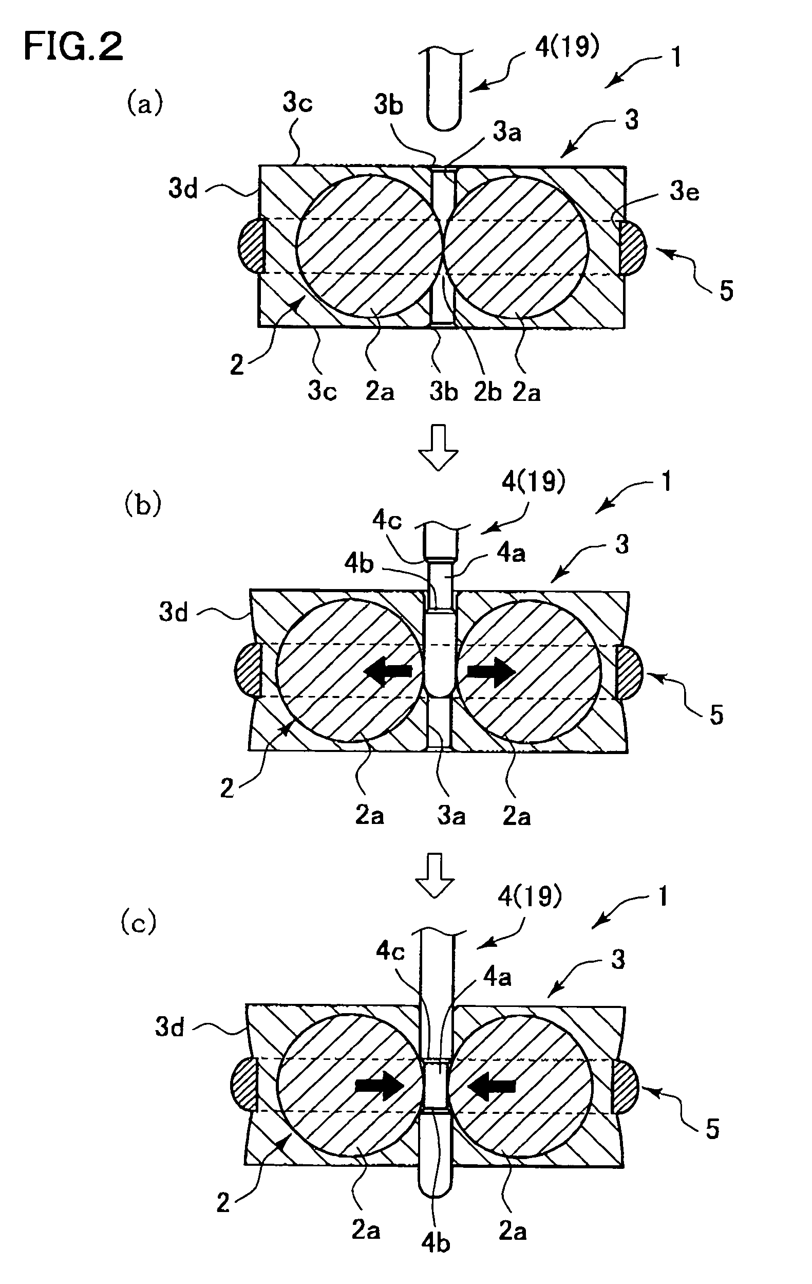
[0073]Now, embodiments of the present invention will be described with reference to some examples shown in the accompanying drawings. FIG. 1A and FIG. 1B each show a first embodiment of each of a pierced earring fastener serving as a fastener according to the present invention and a pierced earring as an ornament. A pierced earring fastener 1 (fastener) comprises: a pinching member 2 comprised of three (a plurality of) balls 2a, 2a and 2a; a ball holder (holder) 3 that is a rubber-like elastic member; and a ring 5 (restraining member) for tightening the pinching member 2 and the holder 3.
[0074]The three balls 2a, 2a and 2a are disposed in a ring shape at intervals of 120 degrees in a circumferential direction, as elements constituting the pinching member 2. These balls are retained at their predetermined positions by means of the holder 3. The ball 2a is formed in a spherical shape, of a hard metal material (for example, stainless steel). The holder 3 is formed in a cylindrical shap...
second embodiment
[0082]FIG. 4A and FIG. 4B each show a second modified example of a pierced earring fastener. In FIG. 4A and FIG. 4B, the pinching member 2 is comprised of the two balls 2a and 2a opposed to each other in a circumferential direction at an interval of 180 degrees.
third embodiment
[0083]FIG. 5A and FIG. 5B each show a third embodiment of a pierced earring fastener. In FIG. 5A and FIG. 5B, the pinching member 2 is comprised of two cylinder bodies 2a′ and 2a′ integrally coupled with each other. At the time of insertion molding of the holder 3, silicone rubber is filled inside of the cylinder bodies 2a′ and 2a′. In addition, an upper end face 3c′ of the holder 3 is formed into an upwardly protrusive dome shape. In the second embodiment (FIG. 4A and FIG. 4B) and the third embodiment (FIG. 5A and FIG. 5B), constituent elements having functions common to those of the first embodiment (FIG. 1A to FIG. 3) are designated by the same reference numerals, and the descriptions are omitted.
PUM
 Abstract
Description
Claims
Application Information
 - R&D
- Intellectual Property
- Life Sciences
- Materials
- Tech Scout
- Unparalleled Data Quality
- Higher Quality Content
- 60% Fewer Hallucinations
Browse by: Latest US Patents, China's latest patents, Technical Efficacy Thesaurus, Application Domain, Technology Topic, Popular Technical Reports.
© 2025 PatSnap. All rights reserved.Legal|Privacy policy|Modern Slavery Act Transparency Statement|Sitemap|About US| Contact US: help@patsnap.com


