Solenoid control device

a technology of solenoid control and control device, which is applied in the direction of positive displacement liquid engine, magnetic body, machine/engine, etc., can solve the problems of water breaking between the two members, the one-piece forming of the housing increasing the fabrication cost, and the complex structure of the connection, etc., to achieve the effect of no peeling of the anti-corrosion plating

Active Publication Date: 2009-11-03
EAGLE INDS
View PDF22 Cites 7 Cited by
  • Summary
  • Abstract
  • Description
  • Claims
  • Application Information

AI Technical Summary

Benefits of technology

[0013]According to the solenoid control valve of the present invention, the upper plate is fittingly engaged with the casing main body. And a first attracting element (fixed iron core) attracts a second attracting element (moveable iron core) thereto with magnetic flux. The magnetic flux, at the same time, is passed from the second attracting element through the upper plate to the casing main body. The flux further reaches from the casing main body to the first attracting element for closing the magnetic circuit. Under this arrangement, a seal portion provides a seal against an outside surface at between the fitting surfaces of the upper plate and the casing main body, and thereby water is prevented from breaking into the solenoid coil side. This arrangement permits axial length of the fitting portion in the connector to be determined in accordance with a fit length between the engagement surface on the upper plate and the fitting surface on the joint portion. Therefore the length of the fitting portion in the connector can be made small. In addition, a seal can easily be provided by attaching a seal portion into the outside surface which is formed at between the casing main body and the upper plate. Moreover, since the joint portion and the flange portion can be fitted to each other without O-ring, the fitting surfaces are kept in a good contact with each other and thereby electric conductivity between the upper plate and the casing main body is enhanced. Further, not only forming process of the connector becomes straightforward but also assembly cost of the casing main body and the connector mounting the upper plate is reduced.
[0016]According to the solenoid control valve of this embodiment, the fitting surface and the support surface are formed in a step shoulder design on the inner circumference of the joint portion, and the upper plate is kept in a seal contact with the fitting surface and the support surface, and moreover, the free end portion of the joint portion is inclined to the upper plate side for the purpose of fixing the joint portion against the upper plate. Thereby a seal tight contact of the two members can be achieved and electric conductivity between the upper plate and the casing main body is enhanced. In addition, the seal portion which is attached to the outside surface at between the joint portion and the upper plate can prevent water from breaking into the solenoid coil side. The step shoulder design of the joint portion of the casing main body allows its end portion to be arranged in a thin wall, and an inclination angle of the end portion can be made less than 5 degrees. Therefore no peeling problem of the plating occurs and a secure engagement of the joint portion to the upper plate can be achieved.
[0018]According to the solenoid control valve of this embodiment, as the seal portion is made of silicone potting a seal can easily be provided at between the fitting surfaces on end portion of the casing main body and on the upper plate. Also use of silicone potting for the seal portion only requires the application of the silicone potting to an upper portion of the fitting surfaces between the upper plate and the casing main body. Thus there is no need of having a base portion of long length for mounting an O-ring. And further, since no O-ring groove needs to be prepared, not only a longitudinal length of the solenoid control valve can be shortened but also manufacture cost can be reduced.
[0020]According to the solenoid control valve of this embodiment, only a slight inclination of the end portion of the casing main body suffices to fixate the upper plate relative to the casing main body and a rubber-made ring of square cross section can be used for installation, and thereby a seal can be provided at the fitting surfaces between the upper plate and the casing main body. Moreover, since the inclination of the end portion can be formed under the presence of the support from the seal portion, no excessive bending occurs to the end portion. As a result, no peeling of anti-corrosion plating will occur.

Problems solved by technology

Also this connector tends to become complex in structure because of necessary deposition of an intermediate ring in order that the connector and the housing may be press formed in one-piece.
The press forming of the housing in one-piece increases its fabrication cost.
Because the cylindrical portion of the connector and the casing main body are merely kept in a fitting relation, thermal expansion of the resin-made connector may cause water to break into between the two members.
Forming the connector and the casing main body in one-piece necessarily makes the structure more complex, and thereby its manufacture cost is increased.
This may impose a problem on the solenoid control valve when it is to be installed in an apparatus requiring downsizing.
When the rust on the end portion 103A grows and reaches the O-ring, seal performance of the O-ring is deteriorated.
There is, however, no seal provided thereat so that there remains a danger of water breaking into the solenoid coil side from the clinching portion.
In particular, when a casing main body or connector cap is treated with plating for anti-corrosion purpose, inflection for the clinching may cause peeling off of the plated portion.
Such a plate peeling may induce a further growth of corrosion at the clinching portion and allow water therefrom to break into the solenoid coil side.
Although the casing main body is fitted to an upper plate or the cylindrical portion of a connector, the two members are fixed to each other only under a fitting friction, and therefore sealing ability at between the casing main body and the upper plate or the cylindrical portion of a connector is weak such that water may break into the solenoid coil side from between the fitting surfaces.

Method used


Image

  • Solenoid control device
  • Solenoid control device
  • Solenoid control device

Examples


Embodiment Construction

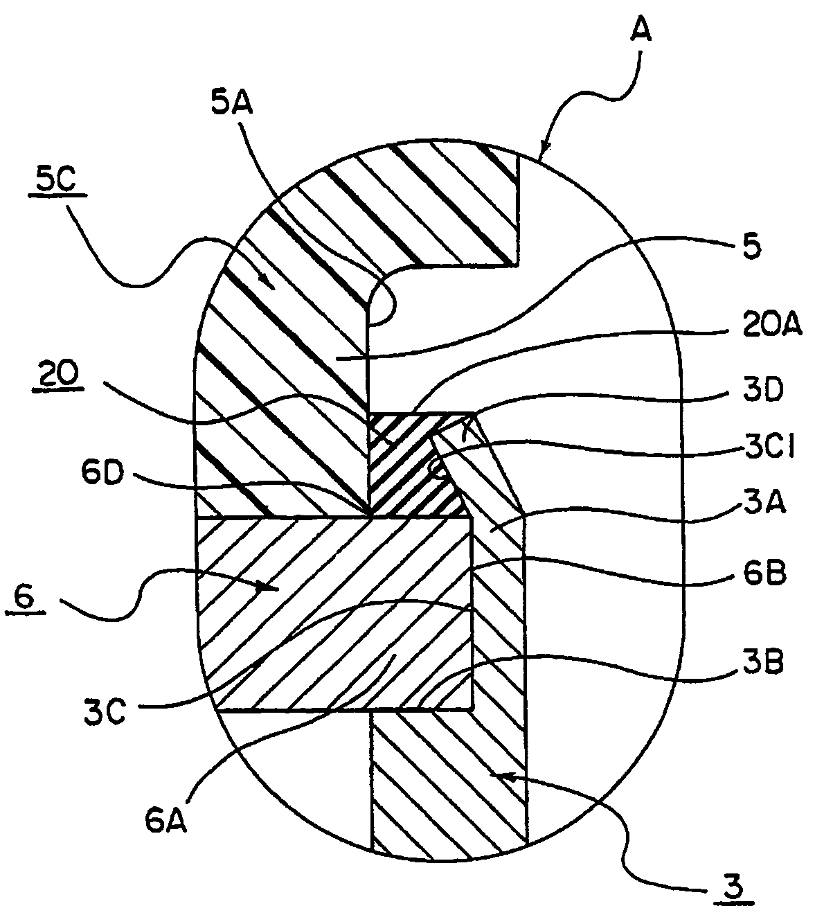
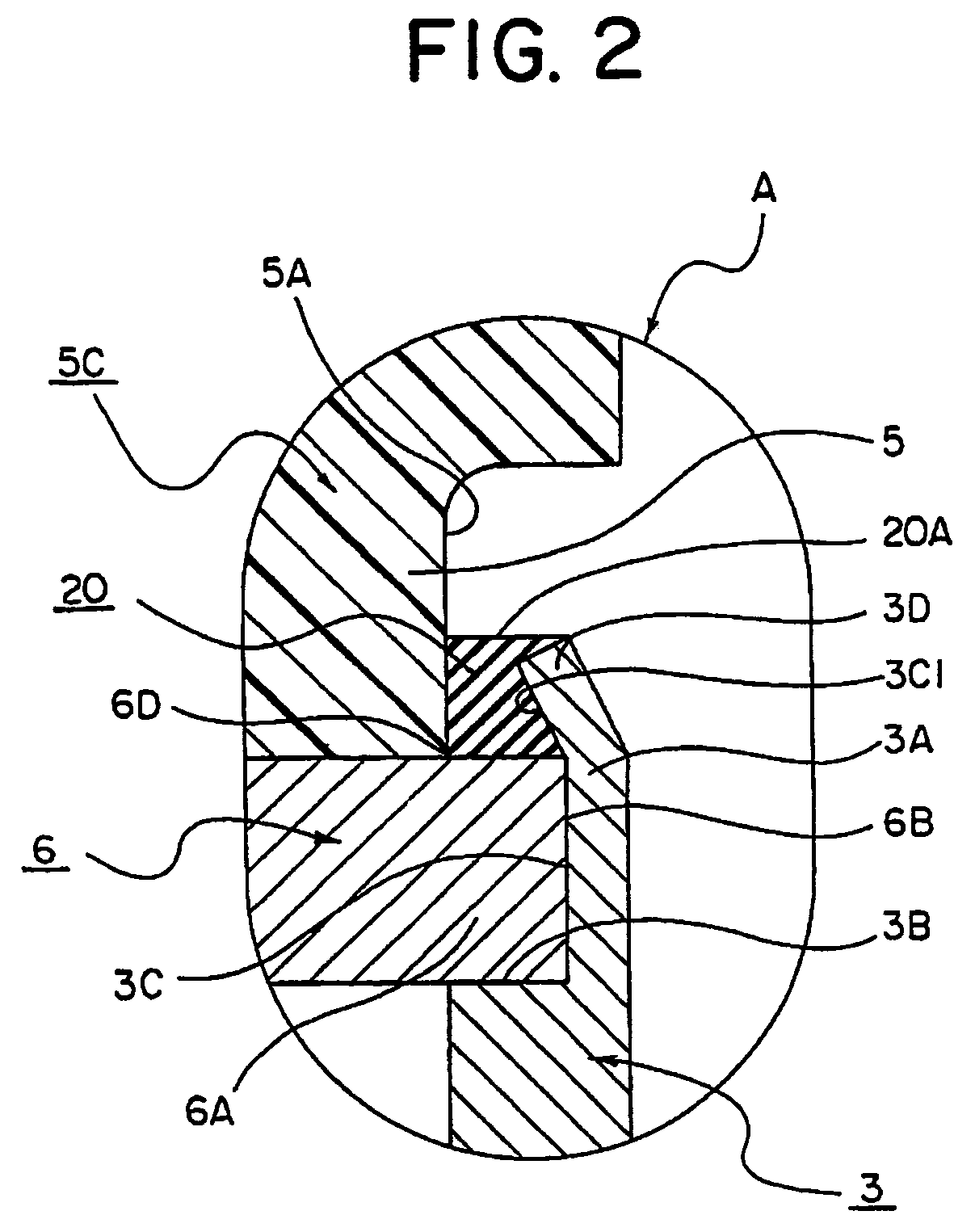
[0024]Described below is the details of the figures of a preferred embodiment in accordance with the principles of the present invention. All the figures explained below are constructed according to actual design drawings with accurate dimensional relations.

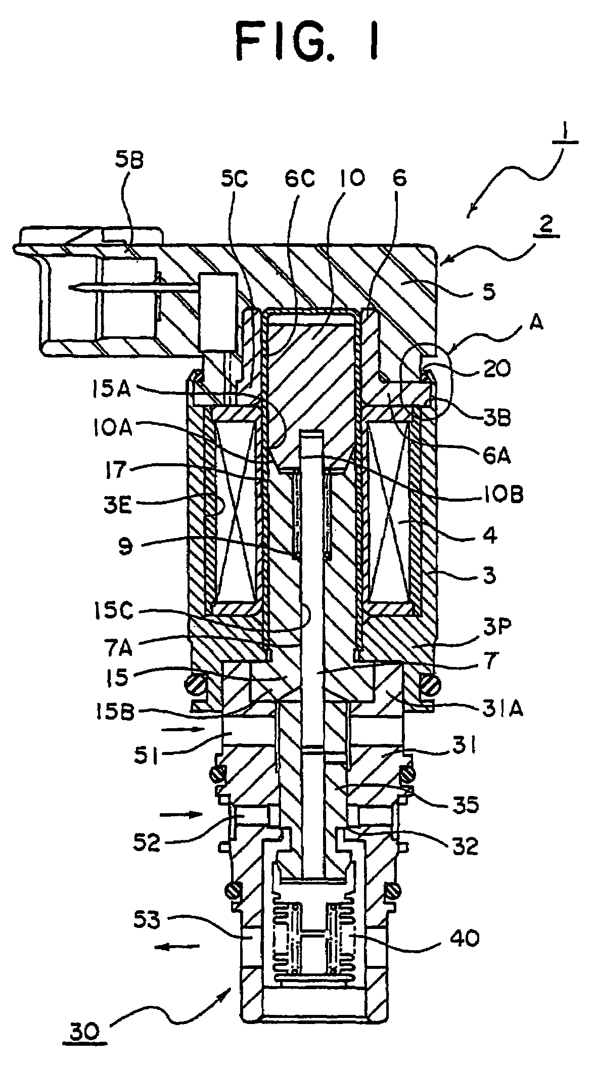
[0025]FIG. 1 is a cross sectional view of a solenoid control valve showing a preferred embodiment relative to the present invention. Reference numeral 1 in FIG. 1 signifies a solenoid control valve. The solenoid control valve 1 is so constructed that a solenoid portion 2 is connected with a valve portion 30. The valve portion 30 disposes a valve housing 31 which defines the outer shape of the valve portion. The valve housing 31 forms a through hole therewithin. And the valve housing 31 is made of metal such as brass, aluminum, stainless or the like, synthetic resin, or the like.

[0026]The valve housing 31 has a valve chamber in a large diameter which is located above the through hole in the figure. There is disposed a connecting p...


PUM


Abstract

A case main body and an upper plate are reliably fitted together, a seal is formed between the fitting surfaces, and a magnetic circuit is prevented from malfunctioning. A solenoid-controlled valve, which connects a solenoid section (2) and a valve section (30), comprises a cylindrical case main body (3) having a solenoid coil (4) housed therein and having a connecting section (3A) at one end, an upper plate (6) having a locking surface (6B) adapted to be fitted to the connecting section (3A), and a connector (5) integrally provided with the upper plate (6). A seal section (20) is joined to an outer surface between the fitting surfaces of the connecting section (3A) and the upper plate (6).

Description

TECHNICAL FIELD[0001]The present invention relates to a solenoid control valve. More particularly, the invention relates to a solenoid control valve which enhances performance of the solenoid portion and reduces the assembly cost by improving a connecting structure of the casing main body and the upper plate.BACKGROUND ART[0002]The present invention relates to an improvement technology over solenoid control valves as prior art. The solenoid control valve as a first prior art is shown in FIG. 3. FIG. 3 represents a relative art of the present invention which is used as a solenoid control valve for a compressor or the like.[0003]In FIG. 3, a valve portion 130 given in the lower part of the figure and a solenoid portion 101 are connected with each other by fitting the outer diameter surface on the upper side of a casing main body 103 to a mount borehole, which is located at the lower end of the casing main body 103 of the solenoid portion 101. And the solenoid portion 101 is assembled ...

Claims


Application Information

Patent Timeline
Patent Type & Authority Patents(United States)
IPC IPC(8): F16K31/06
CPCF04B27/1804F16K31/0668F16K31/0613F04B2027/1827F04B2027/1854F04B2027/1831
Inventor IWA, TOSHIAKISASAKI, SHINJIHIRATA, ICHIROUEMURA, NORIO
Owner EAGLE INDS
Why Eureka
Try Eureka