
Table

a technology for tables and legs, applied in the field of furniture pieces, can solve the problems of difficult leg attachment, and achieve the effect of small size and simple manipulation

Active Publication Date: 2009-11-03
MILLERKNOLL INC
View PDF53 Cites 2 Cited by
  • Summary
  • Abstract
  • Description
  • Claims
  • Application Information

AI Technical Summary

Benefits of technology

[0005]One object of this invention is to provide a piece of furniture of the type mentioned above but in which each leg or each support can be dependably and solidly attached with as small as possible a cost outlay and with simple manipulation.
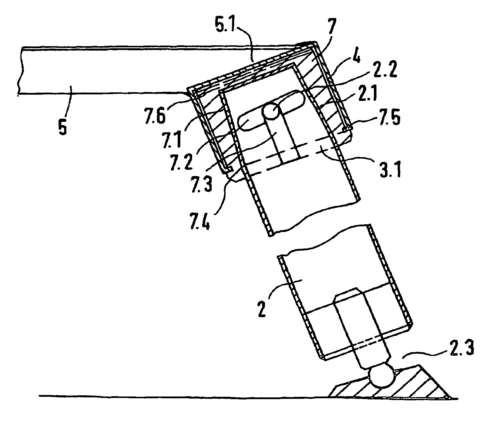
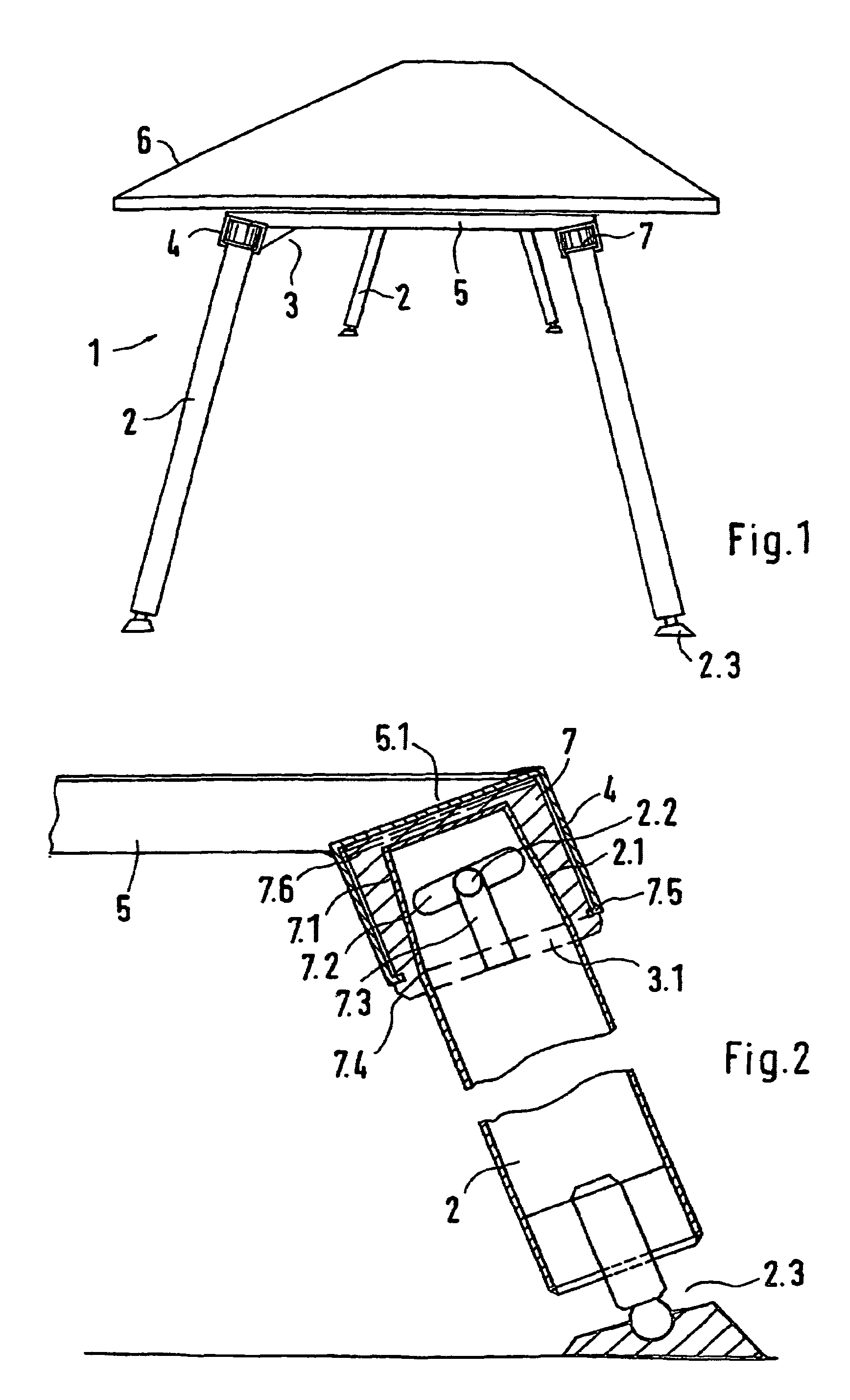
[0007]Some engagement elements in the form of helical segments are formed in the receivers on a respectively at least partially encircling inside, and counter-engagement elements are formed on the respective outside of the end sections, which work together for fixing the legs in place free of play. In the opposite way, the engagement elements in the form of spirals are formed at the end sections and the counter-engagement elements in the receivers. With the engagement elements in the form of helical segments and the counter-engagement elements matched to them, it is possible to attach the legs or supports dependably and solidly to the frame without additional further elements and by simple manipulation, wherein the clamping of the legs in the receivers takes place by a simple insertion and turning movement. Simple release by turning is also possible.
[0011]The steps, wherein the receivers in the form of separate inserts made of plastic or metal are fixed in place in respectively matched recesses in linear profiled elements or transverse struts of the support structure, for example in the shape of a frame, are also advantageous for manufacturing and a simple structure.
[0012]A simple construction is possible if the linear profiled elements and / or the transverse struts are embodied as hollow profiled elements which, for introducing the inserts, have openings on their underside which are matched to the exterior cross section of the inserts. Thus, it is possible to use simple basic elements for constructing the frame.
[0015]The linear profiled elements are designed as four-edged hollow profiled sections and thus contributes to a simple structure.

Problems solved by technology

Although, as a result of the separate attachable legs, such tables can be stored in small packaging units and transported, the attachment of the legs is not easy, in particular in the event of large clamping forces, or if not solid in case of low insertion forces.

Method used


Image

  • Table
  • Table

Examples


Embodiment Construction

[0020]As shown in FIG. 1, the piece of furniture in the form of a table has a table frame 1 with a support structure in the form of a frame 3 supported on legs 2, which is formed by linear profiled elements 4, spaced apart parallel and transverse struts 5 connecting them, and which solidly supports a preferably rectangular table top 6 on its top attached to the two linear profiled elements 4 and / or the transverse struts 5. Here, the linear profiled elements 4 are offset from a center line respectively in the direction toward the front and toward back of the table top 6, so that a solid seating of the table top 6 results. The linear profiled elements 4 are designed as closed four-edged hollow profiled sections with a rectangular or square cross section. The transverse struts 5 can also have profiled sections rectangular in cross section, and can be designed to be relatively flat, such as of a relatively large width in comparison with their height, so that a relatively large surface f...


PUM


Abstract

A piece of furniture, for example, a table, having a frame, supported on legs and carrying a table top, embodied with two parallel separate longitudinal profiles and at least two connected transverse struts and which has hollow recesses, accessible from an underside thereof, for the upper end sections of the legs. A simple and stable leg fixing is thus achieved, whereby coil-section shaped contact elements are arranged on circumferential inner surfaces in the recesses, and contact elements, cooperating with the above for a play-free fixing of the legs, are arranged on the external surface of the end sections, or conversely the spiral section shaped contact elements are embodied on the end sections and the contact elements are embodied in the recesses.

Description

BACKGROUND OF THE INVENTION[0001]1. Field of the Invention[0002]This invention relates to a piece of furniture, such as a table, a chair or a stand or the like, having a support structure, which supports a receiving unit and is supported on legs or at least by one support and has hollow receivers, axially accessible from its side, which are at least partially in cross section, for an end section of the leg or the support.[0003]2. Discussion of Related Art[0004]U.S. Pat. No. 4,011,821 teaches a piece of furniture, in particular a table, where the upper end sections of the legs are inserted into cylindrical receivers and are fixed in place on the support structure in the form of a frame of linear and transverse profiled sections. Although, as a result of the separate attachable legs, such tables can be stored in small packaging units and transported, the attachment of the legs is not easy, in particular in the event of large clamping forces, or if not solid in case of low insertion fo...

Claims


Application Information

Patent Timeline
Patent Type & Authority Patents(United States)
IPC IPC(8): A47B47/00A47B13/02
CPCA47B13/021
Inventor KORB, DANIEL
Owner MILLERKNOLL INC
Learn More