System for mobile broadband networking using dynamic quality of service provisioning

a mobile broadband network and dynamic quality technology, applied in the field of network communication, can solve the problems of difficult to provide services, inability to gain access to the corporate ethernet network or internet connection, and inability to guarantee the quality of a communications channel in the wireless network, so as to achieve the effect of reducing power consumption, increasing receiver sensitivity to specific units at known locations, and reducing distan

Inactive Publication Date: 2009-10-27
CHIGUSA TADAAKI
View PDF116 Cites 19 Cited by
  • Summary
  • Abstract
  • Description
  • Claims
  • Application Information

AI Technical Summary

Benefits of technology

[0013]One feature of the wireless system of the present invention is a routing process that tracks unit locations and inter-unit channel conditions. The routing process uses characteristics of the channels between two or more units, such as but not limited to, the data rate, reliability, number of unit hops, load, congestion, requested Quality of Service (QoS), etc. Additional factors can be used in routing evaluation, such as, desired QoS to be provided to a user, device or process. For example, where a user is using a voice feature of a device, the routing process attempts to ensure at least a minimum data rate or time delay with no dropouts to make sure the voice quality is maintained. This feature has a higher level of service than, for example, downloading a file since a pause in file downloading does not have as critical an effect on the user. One advantage of the present invention is the capability to determine the required level of service based upon the feature requested by the user of the network. Therefore, the user does not have to be concerned about the network conditions, whereas, in other networks, the user may have to stop the conversation or take other actions until the radio conditions improve.
[0014]Other aspects of the routing process include registration or detection of transceiver location. Where fixed units are installed in homes, the user can manually describe the location so that, for example, latitude and longitude coordinates could be derived. A built-in GPS receiver could also perform the same task. Another approach is to triangulate transceiver location by using the positions of multiple known transceivers. Data about various characteristics of units that is useful for routing purposes is maintained in tables (or other forms of storage) in various units, in a central location or both. Such tables are propagated throughout the network as needed. As units are brought into, taken from, or moved within the network, the routing process (or processes) attempts to maintain desired levels of service.
[0015]One feature of the RF transmitters used in the present invention is the use of antenna arrays for directional transmission. This allows transmitters so-equipped to “steer” a radio beam to specific receivers so that greater distance with less power is achieved. The receiving ability of such antennas is also directional so that receiver sensitivity to specific units at known locations can be increased. Further, this approach reduces the interference from potentially competing signals. This, in turn, increases network efficiency and can, therefore, enhance network density and performance.
[0016]Units can be connected to other wireless or wired networks, such as but not limited to, the Internet, corporate or campus intranets, home networks, etc. Services, such as, streaming of media can be provided within a household or to other friends or users. Security and access controls are provided. One aspect of the system allows units to relay information without storing the information in order to comply with typical media licenses or copyrights. The system provides flexible permission granting, control and other features to manage use of media, objects or other data.
[0017]Generally, all the data can be relayed securely without any ability to interpret data that is in transit through a node or nodes. The system allows for end-to-end encryption to protect traffic being routed along the communication route. Alternatively, some portions or links of the communication route are protected with encryption while other portions are not, and different portions of the communication route can be protected using different encryption codes or technologies. This is advantageous for a number of reasons. For example, in order to comply with certain country specific regulatory or other issues, it may be necessary to terminate the secure link at one or more intermediary nodes and then forward the traffic using a different encryption code or in clear text; in another instance, it may also be required to re-encrypt the already encrypted channel with another encryption code.
[0018]Other aspects of the present invention include user interfaces of the units, scalability of the network, etc.

Problems solved by technology

There is no means of gaining access to the corporate Ethernet network or an Internet connection.
Generally, the quality of a communications channel in a wireless network is not guaranteed so that, for example, a software process executing on a device is not guaranteed a specific transfer rate over any given interval of time.
This makes it very difficult to provide services that require a consistent bit or packet error rate (BER or PER); services such as streaming media, video and audio fall into this category.
Other approaches to wireless communications do not provide a comprehensive system design approach.
Bluetooth does include several features for point-to-point communications between devices, but does this based on a master-slave relationship that is difficult to use in a network with changing topology, such as one made up of mobile wireless transceivers.
This clearly limits the operational range of the network.

Method used


Image

  • System for mobile broadband networking using dynamic quality of service provisioning
  • System for mobile broadband networking using dynamic quality of service provisioning

Examples


Embodiment Construction

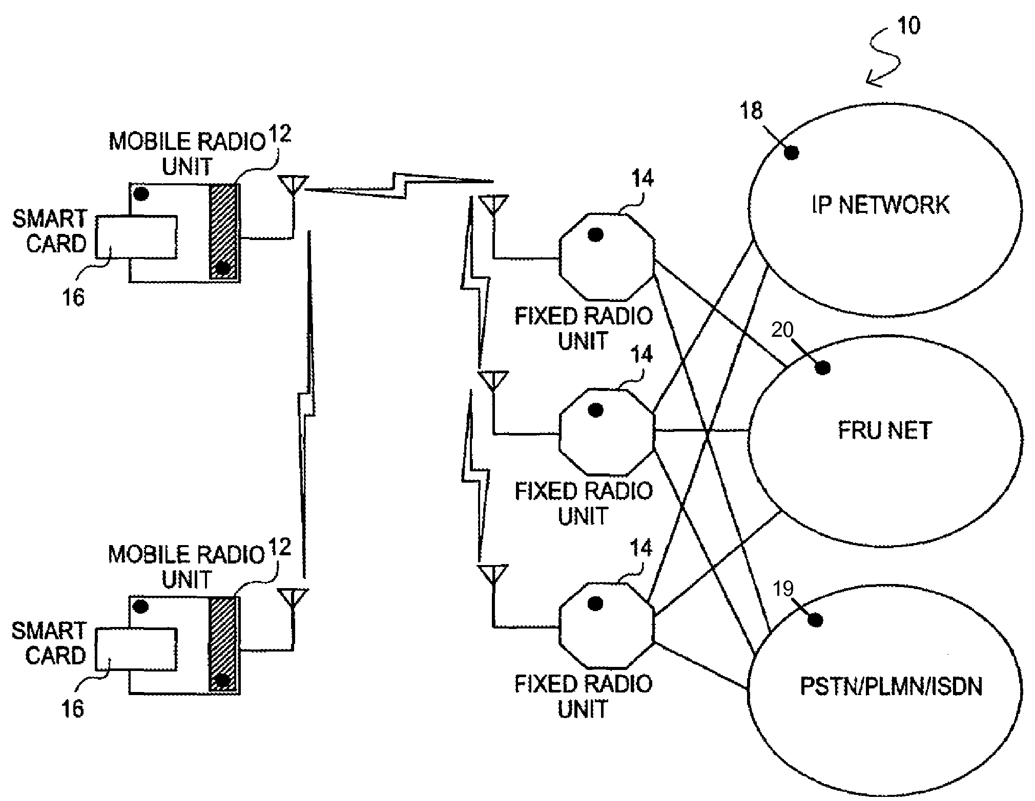
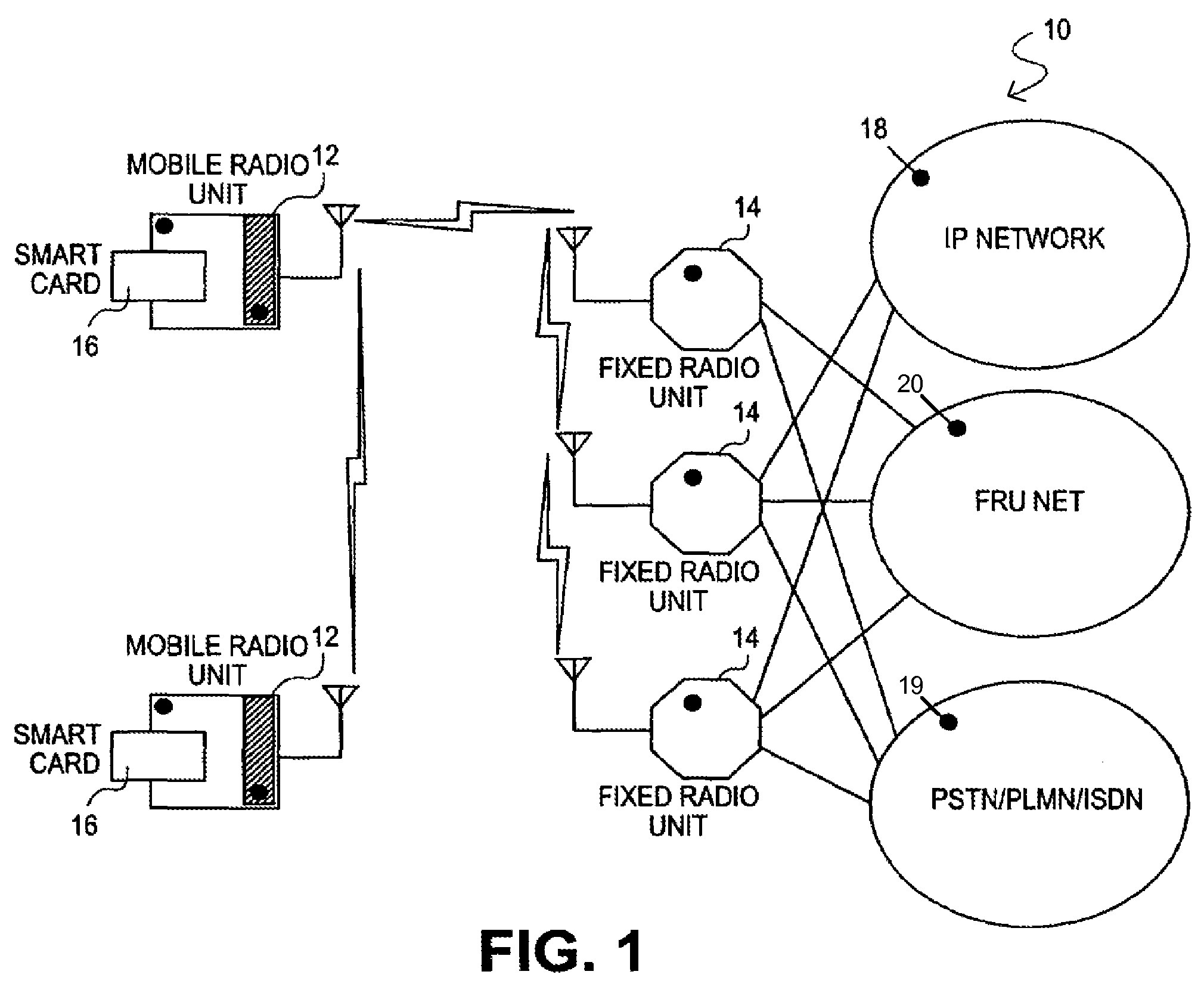
[0021]The present invention in the form of one or more exemplary embodiments will now be described. FIG. 1 is a simplified schematic block diagram illustrating one exemplary embodiment of the present invention. In this exemplary embodiment, the network 10 includes a number of mobile radio units (each an MRU) 12 and a number of semi-fixed or fixed radio units 14 (each an FRU). Based on the disclosure and teachings provided herein, a person of ordinary skill in the art will appreciate that other types of devices that are able to send and receive signals, i.e., transceivers, can be used as MRUs or FRUs in accordance with the present invention.

[0022]In one exemplary embodiment, the MRU 12 is a user portable device that is capable of handling wireless communications. The MRU 12 includes two types of high bandwidth radio, one is used for long range relay communication and the other for short range local communication. The MRU 12 is capable of communicating with nearby MRUs and FRUs 14. Th...


PUM


Abstract

A wireless networking system uses mobile and fixed transceivers to achieve a network with changing topology. A routing process includes quality-of-service considerations in the network to allow for features such as file or other data transfer, streaming audio and video, digital telephone communications, etc. The routing process adapts to transceiver units entering, leaving, or moving within, the network. Auxiliary networks such as the Internet, campus or corporate intranets, home networks, etc., can be accessed through the wireless network. Features, designs and user interfaces for the units are described. Security and access control of media content and other data is presented.

Description

CROSS-REFERENCES TO RELATED APPLICATION(S)[0001]The present application claims the benefit of priority under 35 U.S.C. §119 from U.S. Provisional Patent Application Ser. No. 60 / 403,786 entitled “SYSTEM FOR MOBILE BROADBAND NETWORKING USING DYNAMIC QUALITY OF SERVICE PROVISIONING”, filed on Aug. 14, 2002, the disclosure of which is hereby incorporated by reference in its entirety for all purposes.BACKGROUND OF THE INVENTION[0002]The present invention relates in general to network communications and, more specifically, to a system having fixed and mobile wireless transceivers with dynamic routing based on quality-of-service criteria in order to optimize data transfers in a network with dynamically changing topology.[0003]Wireless networks are gaining in popularity. Standards such as 802.11a, 802.11b, 802.11g, Bluetooth, Ultra Wideband (UWB), etc., allow users to connect wirelessly via portions of the radio-frequency spectrum. As the cost of wireless network systems decreases and their...

Claims


Application Information

Patent Timeline
Patent Type & Authority Patents(United States)
IPC IPC(8): H04W40/00H04L12/56H04B7/24H04B7/26H04L12/28H04L29/06H04W88/02
CPCH04L63/0407H04L63/0853H04W88/02H04W92/20H04W88/04
Inventor SAYERS, IANLONG, JAN
Owner CHIGUSA TADAAKI
Why Eureka
Try Eureka