Heat exchanger

a heat exchanger and heat exchange technology, applied in the field of heat exchangers, can solve the problems of low efficiency of work for joining the caps, cumbersome procedure for partitioning, and increasing the number of components, so as to improve heat exchange efficiency and improve heat exchange efficiency

Inactive Publication Date: 2009-10-27
RESONAC HOLDINGS CORPORATION
View PDF12 Cites 9 Cited by
  • Summary
  • Abstract
  • Description
  • Claims
  • Application Information

AI Technical Summary

Benefits of technology

[0021]With the heat exchanger according to par. 1), the header forming plate has an outward bulging portion extending longitudinally thereof and having an opening closed with the intermediate plate. This eliminates the need to use caps for closing opposite end openings unlike the header tank of the above-mentioned publication. As a result, the components can be smaller in number, while the work for joining the caps becomes unnecessary, further obviating the work for making the caps as separate members.
[0023]Furthermore, at least one of all the outward bulging portions serves as a refrigerant passing outward bulging portion for the refrigerant to pass therethrough longitudinally thereof, all the intermediate plate communication holes communicating with the refrigerant passing bulging portion are held in communication by communication portions formed in the intermediate plate, these communication holes and the communication portions provide a refrigerant passageway for causing the refrigerant to flow therethrough longitudinally of the refrigerant passing bulging portion, and the refrigerant passageway is altered in cross sectional area along the direction of length thereof by adjusting the width of the communication portions. Accordingly, the quantities of refrigerant to be passed through portions of the passageway are variable as desired. Consequently, the flows of the refrigerant through all the heat exchange tubes can be set at rates which are favorable to achieve improved heat exchange performance. Moreover, the divided flows of refrigerant through, the heat exchange tubes are adjustable in accordance with the flow velocity distribution of the air to be passed through the air passage clearances between the respective pairs of adjacent heat exchange tubes.
[0024]With the heat exchanger described in par. 2), the header forming plate having a bulging portion, the tube connecting plate having tube insertion holes and the intermediate plate having communication holes are each made from a metal plate by press work. This serves to shorten the working time and decrease the number of working steps.

Problems solved by technology

However, the header tank included in the heat exchanger of the publication requires caps for closing opposite end openings and therefore has the problem of necessitating an increased number of components and being low in the efficiency of work for joining the caps to the header member, pipe connecting plate and intermediate plate.
Additionally, the caps must be made as separate members and are cumbersome to make.
To improve the heat exchanger disclosed in the publication in heat exchange performance, it is desirable to change the course of flow of the refrigerant, for example, by dividing the interior of at least one of the header tanks with a partition, whereas this entails the problem that the provision of the partition requires a cumbersome procedure.
The heat exchanger disclosed in the publication further has the problem that all the heat exchange tubes joined to the header tanks are likely to become uneven in the rate of flow of the refrigerant therethrough, consequently exhibiting impaired heat exchange performance.

Method used


Image

  • Heat exchanger
  • Heat exchanger
  • Heat exchanger

Examples


Embodiment Construction

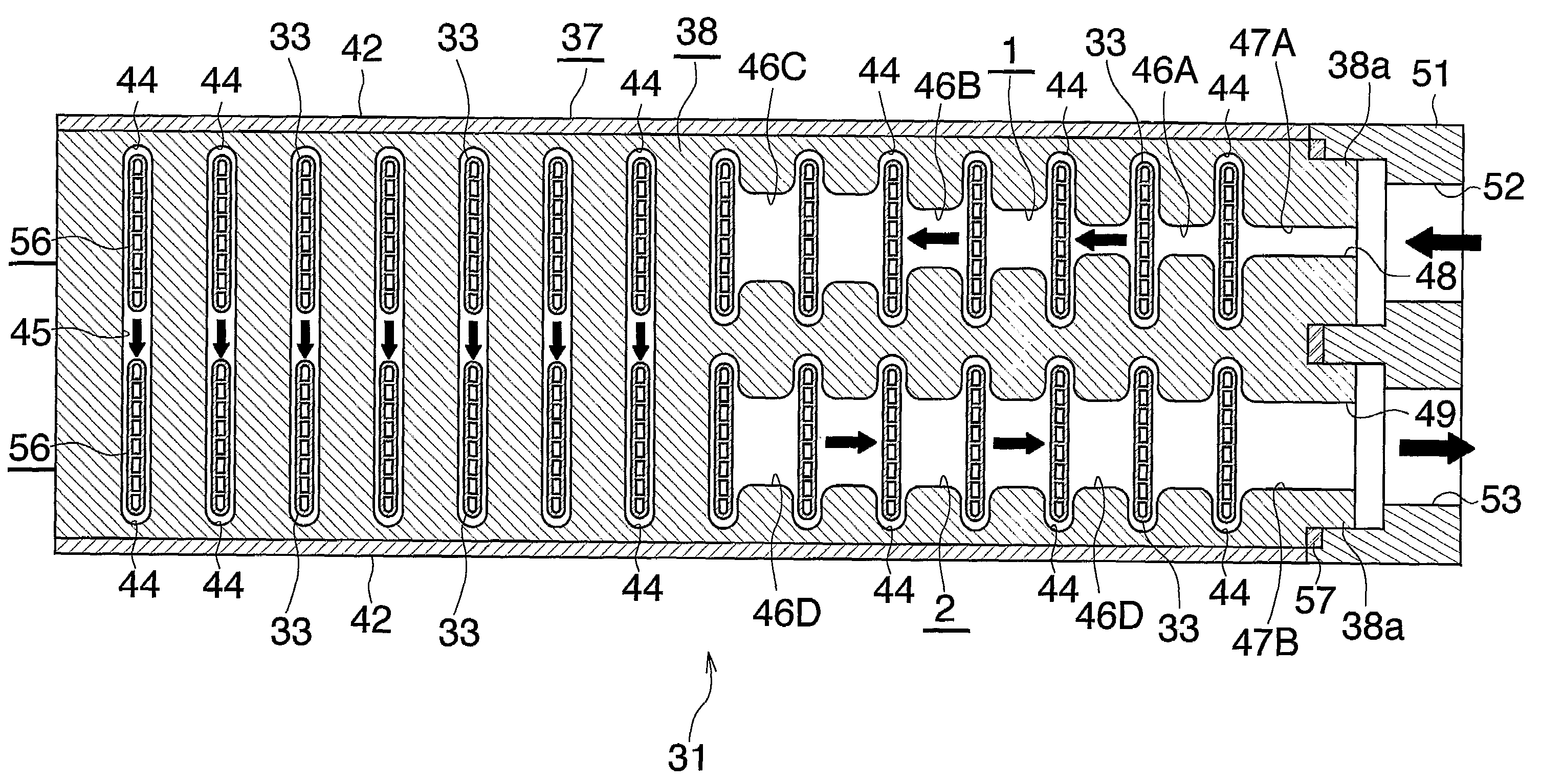
[0045]Embodiments of the present invention will be described below with reference to the drawings. This embodiment is a heat exchanger of the invention as adapted for use as an evaporator for supercritical refrigeration cycles.

[0046]FIGS. 1 to 3 show the overall construction of the evaporator embodying the invention, FIGS. 4 to 9 show the constructions of main portions of the evaporator, and FIG. 10 shows the flow of refrigerant through the evaporator of FIG. 1.

[0047]In the following description, the upper, lower, left-hand and right-hand sides of FIGS. 1 and 2 will be referred to as “upper,”“lower,”“left” and “right,” respectively. Further the downstream side (the direction indicated by the arrow X in FIGS. 1 and 10) of flow of air through an air passing clearance between each adjacent pair of heat exchange tubes will be referred to as the “front,” and the opposite side as the “rear.”

[0048]With reference to FIGS. 1 to 3, an evaporator 30 for use in supercritical refrigeration cycle...


PUM


Abstract

An evaporator has a header tank including a header forming plate with outward bulging portions, a tube connecting plate, and an intermediate plate. Tube insertion holes are formed in the tube connecting plate. Communication holes formed in the intermediate plate cause the tube insertion holes to communicate with the interior of the corresponding outward bulging portion therethrough. At least one of the outward bulging portions allows a refrigerant to flow therethrough longitudinally. All the communication holes in communication with the refrigerant passing bulging portion are held in communication by communication portions for the communication holes, the communication portions providing a refrigerant passageway. The refrigerant passageway is altered in cross sectional area along the longitudinal direction thereof by adjusting the width of the communication portions.

Description

CROSS REFERENCE TO RELATED APPLICATION[0001]This application is an application filed under 35 U.S.C. §111(a) claiming the benefit pursuant to 35 U.S.C. §119(e) (1) of the filing date of Provisional Application No. 60 / 562,532 filed Apr. 16, 2004 pursuant to 35 U.S.C. §111(b).TECHNICAL FIELD[0002]The present invention relates to heat exchangers, and more particularly to heat exchangers which are suitable to use as gas coolers or evaporators of supercritical refrigeration cycles wherein a supercritical refrigerant, such as CO2 (carbon dioxide) refrigerant, is used.[0003]The term “aluminum” as used herein and in the appended claims includes aluminum alloys in addition to pure aluminum.BACKGROUND ART[0004]Already known for use in supercritical refrigeration cycles is a heat exchanger comprising a pair of header tanks arranged as spaced apart from each other, heat exchange tubes arranged in parallel at a spacing between the pair of header tanks and having opposite ends joined to the respe...

Claims


Application Information

Patent Timeline
Patent Type & Authority Patents(United States)
IPC IPC(8): F28F9/02F28D1/02F28F1/02F25B1/00F25B39/02F28D1/03F28D1/053F28F27/02
CPCF28D1/0391F28D1/05391F28F9/0278F28F1/022F28F9/0204F28F9/0224F28F9/0246F28D2021/0071F28D2021/0073F28D2021/0085
Inventor ICHIYANAGI, SHIGEHARU
Owner RESONAC HOLDINGS CORPORATION
Why Eureka
Try Eureka