
Chopper-stabilized amplifier and magnetic field sensor

a technology of amplifier and magnetic field sensor, which is applied in the direction of magnetic measurement, amplifier with semiconductor device/discharge tube, instruments, etc., can solve the problems of amplifier saturation, other undesirable effects on the electronic system, and undesirable effects on the system

Active Publication Date: 2009-10-20
ALLEGRO MICROSYSTEMS INC
View PDF8 Cites 100 Cited by
  • Summary
  • Abstract
  • Description
  • Claims
  • Application Information

AI Technical Summary

Benefits of technology

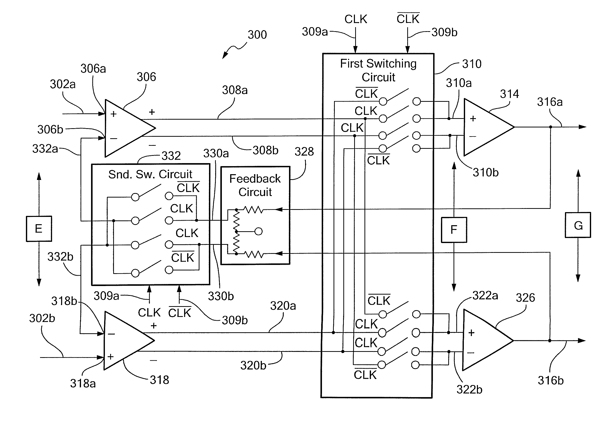
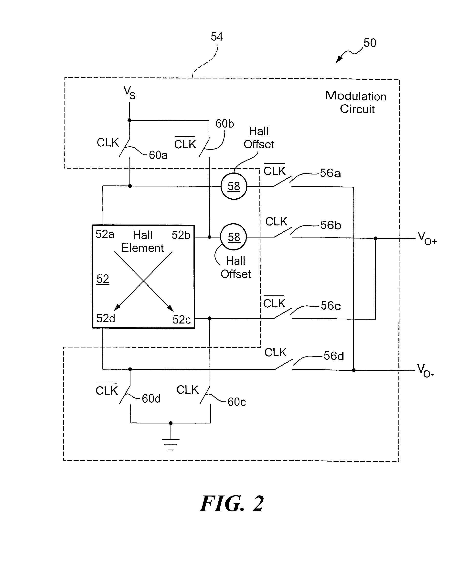
[0014]In some embodiments, a magnetic field sensor includes a Hall element, a modulation circuit, a chopper-stabilized amplifier, and a filter, all coupled in series. The output signal from the Hall effect element can include a magnetic field signal component and an offset component. The modulation circuit is responsive to the output signal of the Hall element and operates to modulate only the magnetic field signal component of the output signal from the Hall element. The chopper-stabilized amplifier is responsive to the modulation circuit output signal and provides an amplifier output signal with a reduced offset component. The chopper-stabilized amplifier has particular characteristics such that the chopper-stabilized amplifier can accommodate a relatively high switching frequency, has a relatively high rejection of a common mode signal, and has a relatively high rejection of an offset component of an input signal.

Problems solved by technology

It will be recognized that, if such an electronic signal is received by and amplified by an amplifier, the amplified offset component might saturate the amplifier or cause other undesirable effects upon the electronic system receiving the electronic signal.
Also, an amplifier itself has an input offset voltage, which, if greatly amplified, can saturate the amplifier or another amplifier or cause undesirable effects upon the system.
A higher switching frequency tends to result in an ability to use a low pass filter with a wider passband, which further tends to result in the magnetic field sensor having a faster response time.
As the low pass filter passband is reduced to reduce the ripple, the response time of the magnetic field sensor increases, which is undesirable.
For example, some conventional chopper-stabilized amplifiers require a relatively low switching frequency, and therefore, as described above, a low pass filter with a relatively narrow passband and a resulting relatively slow response time.
For another example, some conventional chopper-stabilized amplifiers suffer from having a relatively low common mode rejection and / or a relatively low rejection of the offset component.

Method used


Image

  • Chopper-stabilized amplifier and magnetic field sensor
  • Chopper-stabilized amplifier and magnetic field sensor
  • Chopper-stabilized amplifier and magnetic field sensor

Examples


Embodiment Construction

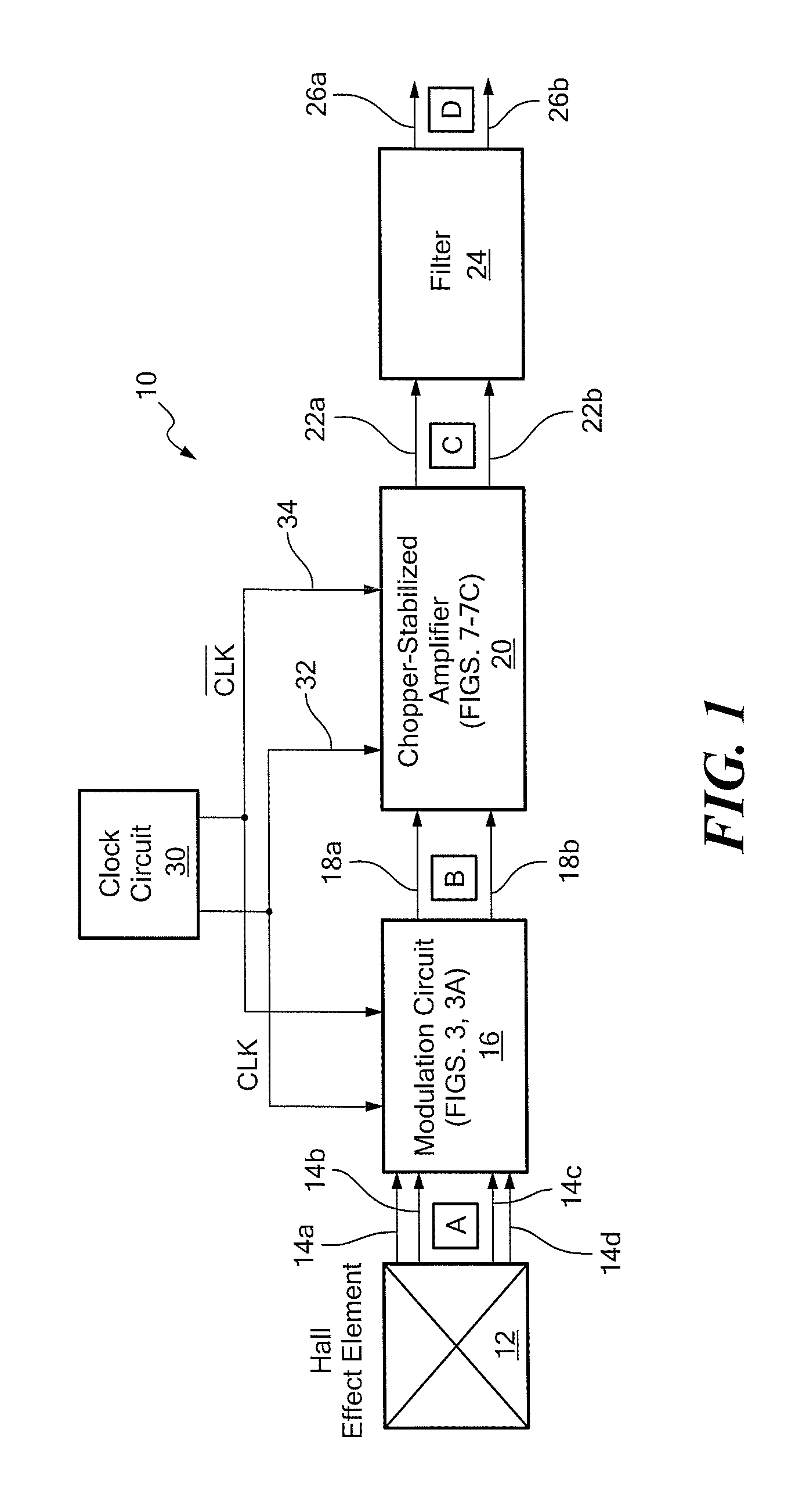
[0038]Referring to FIG. 1, a magnetic field sensor 10 includes a Hall effect element 12 providing four couplings with associated signals 14a-14d to a modulation circuit 16. The modulation circuit 16 can be of a type described below in conjunction with FIGS. 3 and 3A. The modulation circuit provides a differential output signal 18a, 18b to a chopper-stabilized amplifier 20. The chopper-stabilized amplifier 20 provides a differential amplified signal 22a, 22b to a filter module 24. The filter module 24 provides a differential output signal 26a, 26b. In some alternate arrangements, the differential signals 22a, 22b and 26a, 26b can be single ended signals.

[0039]The magnetic field sensor 10 also includes a clock circuit 30 configured to provide a clock signal 32 and a complementary (i.e., inverted) clock signal 34 to both the modulation circuit 16 and to the chopper-stabilized amplifier 20. Therefore, switching function of the modulation circuit 16 is synchronous with function of the ch...


PUM


Abstract

A chopper-stabilized amplifier has switching networks arranged to support a high frequency clocking signal and to provide a high common mode rejection and a high rejection of an offset component of an input signal. A magnetic field sensor includes a Hall effect element coupled to a modulation circuit. The modulation circuit provides a signal to the chopper-stabilized amplifier. The chopper-stabilized amplifier provides an output signal to a low pass filter, which provides an output signal from the magnetic field sensor.

Description

CROSS REFERENCE TO RELATED APPLICATIONS[0001]Not Applicable.STATEMENT REGARDING FEDERALLY SPONSORED RESEARCH[0002]Not Applicable.FIELD OF THE INVENTION[0003]This invention relates generally to chopper-stabilized amplifiers and to magnetic field sensors that use chopper-stabilized amplifiers and, more particularly, to a chopper-stabilized amplifier that can reduce an offset component of an input signal and provide improved common mode rejection while supporting a relatively high switching frequency, and to a magnetic field sensor that uses such a type of chopper-stabilized amplifier.BACKGROUND OF THE INVENTION[0004]As is known, some types of analog electronic signals include both a signal component and an offset component. The offset component is usually an undesirable DC component, while the signal component can be an AC component that usually carries information used by an electronic system that receives the electronic signal. It will be recognized that, if such an electronic signa...

Claims


Application Information

Patent Timeline
IPC IPC(8): H03F1/02
CPCG01R33/072H03F3/45977H03F1/303H03F2203/45212
Inventor ROMERO, HERNAN D.MONREAL, GERARDO
Owner ALLEGRO MICROSYSTEMS INC
Learn More