Method and system for a polarization mode dispersion tolerant optical homodyne detection system with optimized transmission modulation

Inactive Publication Date: 2009-10-06
TERADVANCE COMM
View PDF19 Cites 10 Cited by
  • Summary
  • Abstract
  • Description
  • Claims
  • Application Information

AI Technical Summary

Benefits of technology

[0007]The present invention meets the above objectives by providing an optical homodyne communication system and method in which a reduced amplitude side carrier is transmitted along with data bands in an optical data signal, and upon reception, the side carrier is boosted, shifted to the center of the data bands, and its polarization state is matched to the polarization state of the respective data bands to compensate for polarization mode dispersion during transmission. This scheme achieves the signal-to-noise benefits of homodyne reception without incurring the conventional restrictions and complications of homodyne reception such as requiring the phase of a signal from a local oscillator to be locked to the phase of the optical signal.
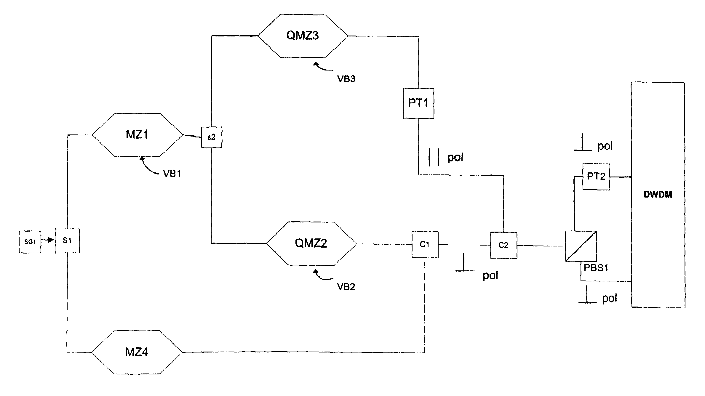
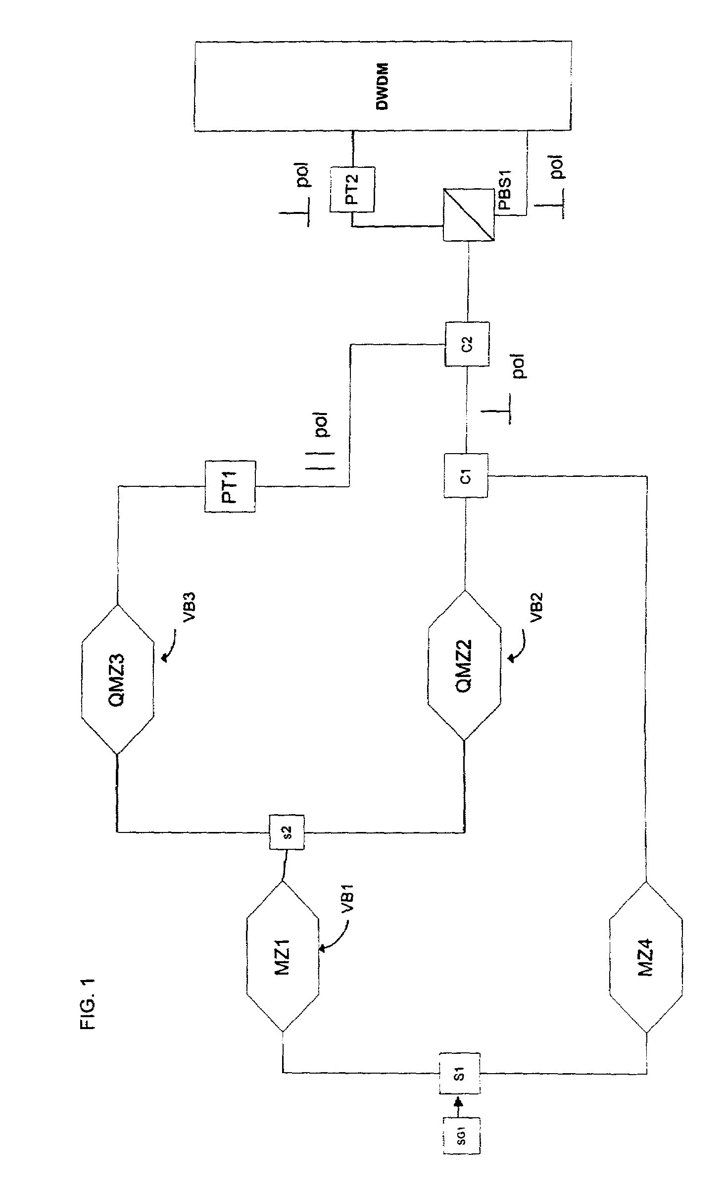
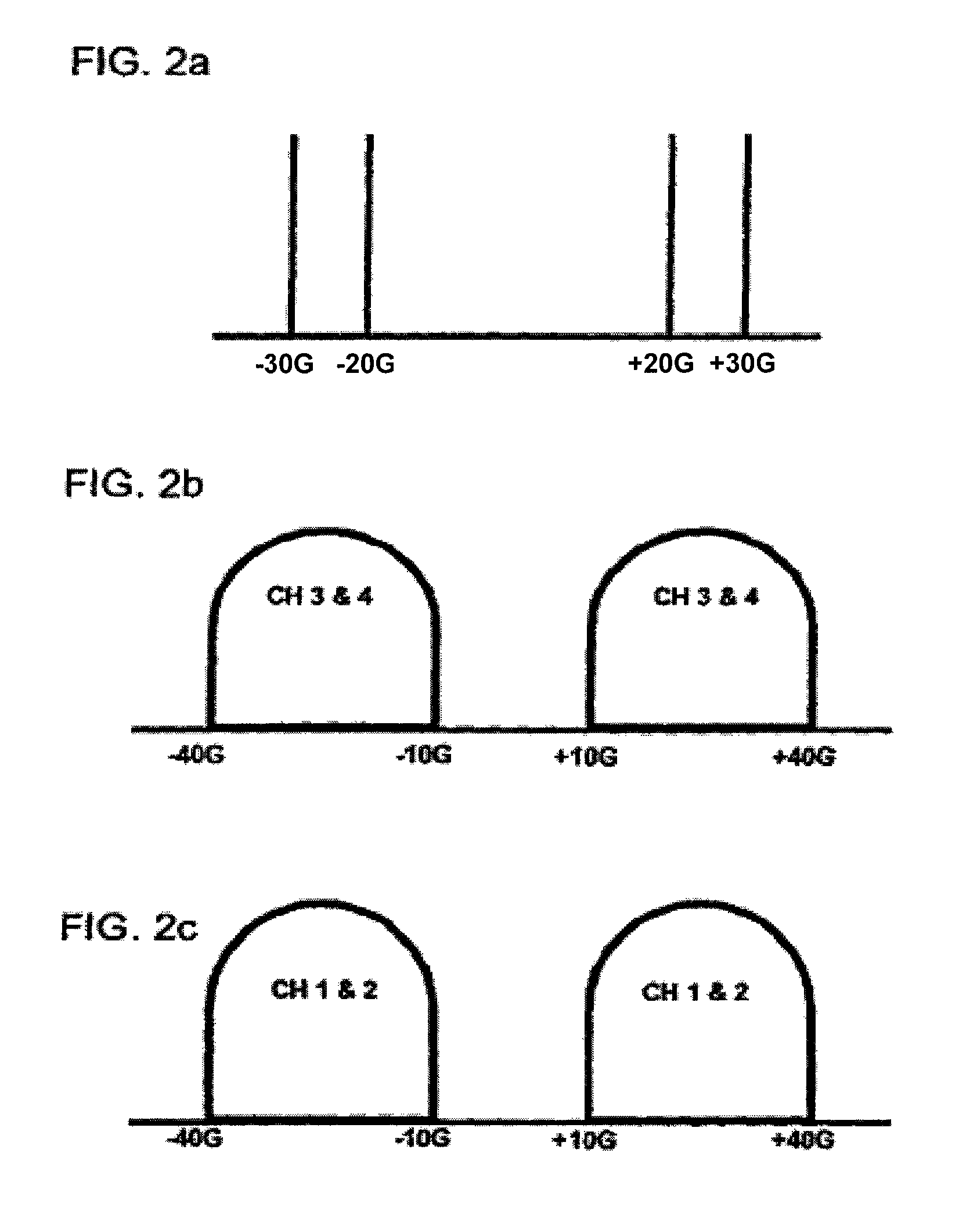
[0008]According to one embodiment, the present invention provides a method of optical communication that begins with providing a quadrature modulated optical data including two data bands separated in frequency, each data band having in-phase and quadrature components. The power of the quadrature modulated optical data signal is limited in order to limit non-linear effects by reducing the power of the optical data signal during transitional states in which data symbols transmitted in the optical data signal change in value, and in particular by reducing the power to zero such that transmitted power decreases to zero at approximately the mid point of the transitional states. The optical data signal is combined with a side carrier at a single frequency between the two data bands of the optical data signal and then transmitted across optical fiber to a receiver.
[0010]The present invention further provides a method of compensating for the effects of chromatic dispersion during transmission over optical fiber by separating the in-phase and quadrature components of the two data bands prior to optoelectric conversion, and, after optoelectric conversion, compensating for chromatic dispersion by applying a corrective function to each of the in-phase and quadrature components of the data bands, the corrective function precisely counteracting the effects of chromatic dispersion on the in-phase and quadrature components.

Problems solved by technology

However, data transmission at 40 Gb / s (or higher) presents extensive design challenges because the effects of polarization mode dispersion (PMD), chromatic dispersion and fiber non-linear effects such as cross-phase modulation become more dominant at the higher transmission rates.
This arrangement requires significant signal processing and differential delays to cover the range of frequencies carrying data.
In addition, in coherent systems typical heterodyne optical reception systems suffer an inherent 3 dB penalty with respect to homodyne systems and introduce phase noise through use of a local oscillator, and thereby add a further level of complexity and constraints to optical system design.

Method used


Image

  • Method and system for a polarization mode dispersion tolerant optical homodyne detection system with optimized transmission modulation
  • Method and system for a polarization mode dispersion tolerant optical homodyne detection system with optimized transmission modulation
  • Method and system for a polarization mode dispersion tolerant optical homodyne detection system with optimized transmission modulation

Examples


first embodiment

[0048]FIG. 5 illustrates an embodiment of a homodyne receiver according to the present invention. An optical data signal is received first by a side carrier boosting module 200 for which the present invention provides two exemplary embodiments. In the side carrier boosting module, shown in FIG. 6, the optical data signal is first input to an optical amplifier EDFA1, which may be, for example, an erbium-doped fiber amplifier (EDFA). It is noted that all further optical amplifiers used in the implementations described below may be implemented as erbium-doped fiber amplifiers. The optical amplifier EDFA1 amplifies the entire spectrum of the received signal by, for example, approximately 15-18 dB. The amplified signal output from EDFA1 is split at S3 between an upper branch that is coupled to a Fabry-Perot resonator FP1 and a lower branch that is coupled to an attenuator ATT1.

[0049]The Fabry Perot resonator FPI functions as a high-Q filter that nearly completely filters out all frequenc...

second embodiment

[0050]the side carrier boosting module, which advantageously makes use of the amplitude-enhancing effect of Stimulated Brillouin Scattering (SBS), is shown in FIG. 7. The SBS effect causes a first optical signal having narrow frequency band around frequency X to be amplified when collides with a signal of frequency X+≈11 GHz traveling in the opposite direction. Referring to FIG. 7, the received signal is input to optical amplifier EDFA3 which amplifies the entire spectrum of the input signal. The signal output from amplifier EDFA3 is transmitted to optical isolator ISL 1, which permits optical signal to travel only in one direction (the direction indicated by the arrow in the figure) and prevents optical signals being reflected or transmitted back toward the amplifier EDFA3. From the optical isolator ISL 1, the optical data signal is split into two branches at splitter S4.

[0051]A first upper branch from splitter S4 leads to Fabry Perot resonator FP2, which passes the side carrier (a...


PUM


Abstract

An optical homodyne communication system and method in which a side carrier is transmitted along with data bands in an optical data signal, and upon reception, the side carrier is boosted, shifted to the center of the data bands, and its polarization state is matched to the polarization state of the respective data bands to compensate for polarization mode dispersion during transmission. By shifting a boosted side carrier to the center of the data bands, and by simultaneously compensating for the effects of polarization mode dispersion, the provided system and method simulate the advantages of homodyne reception using a local oscillator. The deleterious effects of chromatic dispersion on the data signals within the data bands are also compensated for by applying a corrective function to the data signals which precisely counteracts the effects of chromatic dispersion.

Description

CROSS-REFERENCES TO RELATED APPLICATIONS[0001]This application is related to copending and commonly assigned U.S. patent application Ser. No. 09 / 748,750, filed in the United States Patent and Trademark office on Dec. 26, 2000, entitled “Method, System and Apparatus for Optically Transferring Information”.FIELD OF THE INVENTION[0002]The present invention relates to optical data communication, and in particular, relates to a method and optical data communication system that improves signal-to-noise ratio of optical data signals, counteracts polarization mode dispersion and improves robustness to fiber nonlinearities.BACKGROUND INFORMATION[0003]Currently, optical data communication systems are being upgraded from a 10 Gb / s data transmission rate up to a 40 Gb / s transmission rate. However, data transmission at 40 Gb / s (or higher) presents extensive design challenges because the effects of polarization mode dispersion (PMD), chromatic dispersion and fiber non-linear effects such as cross...

Claims


Application Information

Patent Timeline
IPC IPC(8): H04B10/04H04B10/148H04B10/155H04B10/18
CPCH04B10/2513H04B10/2569H04B10/506H04B10/5162H04B10/60H04B10/564H04B10/6151H04B10/6161H04B10/63H04B10/2507H04B10/613
Inventor SCHEMMANN, MARCEL F. C.MARICEVIC, ZORANDJORDJEVIC, ANTONIJE R.RACEY, DARBY
Owner TERADVANCE COMM
Why Eureka
Try Eureka