
DC-AC converter with feedback signal control circuit utilizing power supply voltage, controller IC therefor, and electronic apparatus utilizing the DC-AC converter

a technology of feedback signal and control circuit, which is applied in the direction of dc-ac conversion without reversal, process and machine control, etc., can solve the problems of ccfl damage, inability to shut down the inverter, and discomfort of the viewer, so as to reduce the electric power supplied, prevent the inverter from shutting down, and reduce the effect of undesirable changes in the display condition of the monitor

Active Publication Date: 2009-10-06
ROHM CO LTD
View PDF17 Cites 11 Cited by
  • Summary
  • Abstract
  • Description
  • Claims
  • Application Information

AI Technical Summary

Benefits of technology

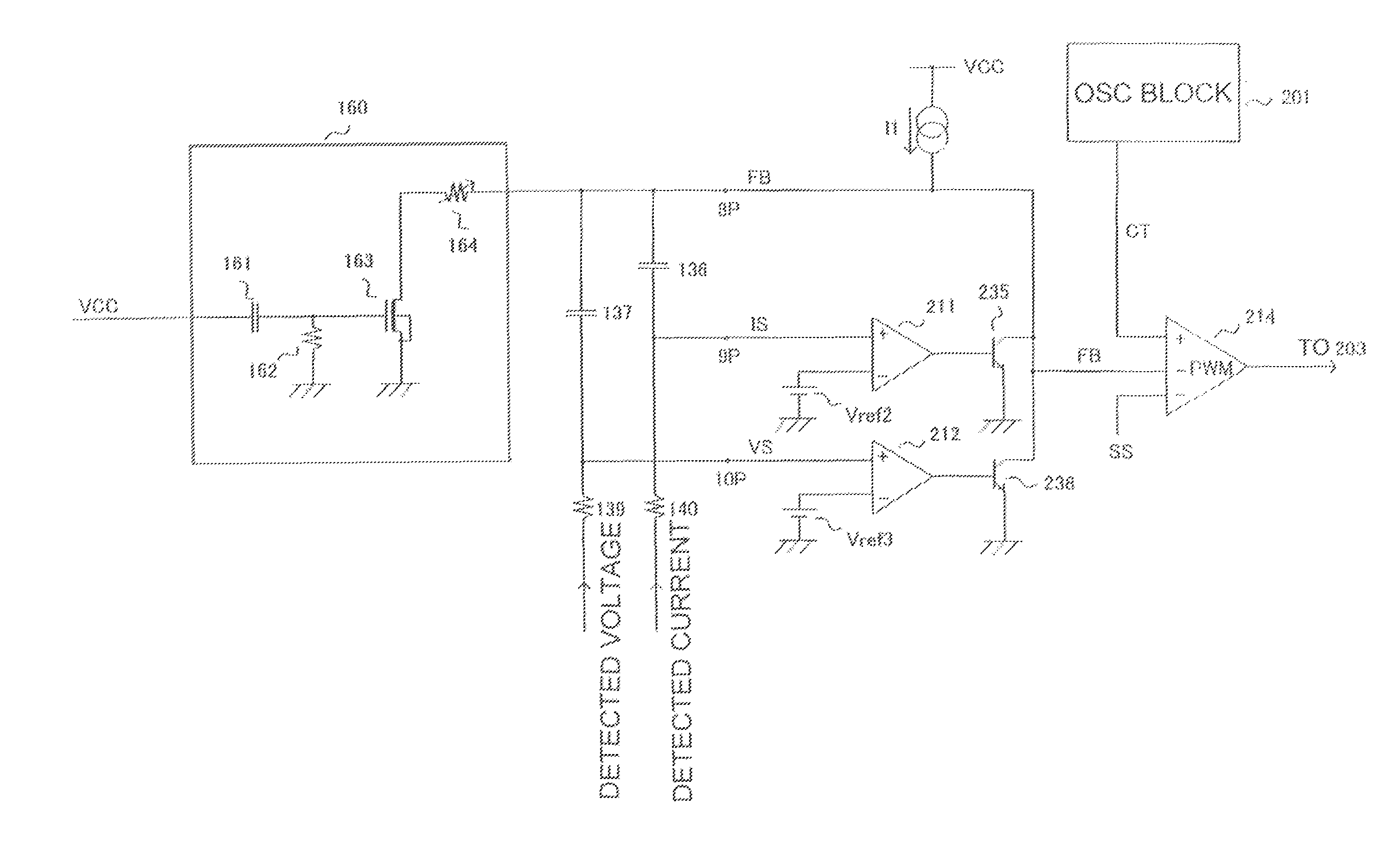
[0031]According to the invention, the current and voltage supplied to a load such as a CCFL are fed back to the inverter to form a current-error signal and a voltage-error signal, respectively, and to form a feedback signal FB based on the magnitudes of the current-error and voltage-error signals. As a consequence, if the DC power supply voltage exhibits a sharp drop, the current and voltage supplied to the load are automatically changed by the feedback signal FB to recover. Thus, shutdown of the inverter that can occur in conventional inverters can be prevented in the inventive inverter.
[0032]In the invention, in the event that the DC power supply voltage sharply rises, the feedback signal FB is changed directly, that is, without waiting for the anticipated change in load current or load voltage, so as to reduce the electric power supplied to the load. Accordingly, undesirable changes in display condition of the monitor can be reduced to suppress viewer's discomfort, and possible damage to the load caused by an over-current can be reduced.
[0033]In order to change the feedback signal FB, it suffices to detect a sharp change in the DC power supply voltage by the differentiation circuit to activate the reduction circuit. Thus, the invention can be realized in a simple structure.

Problems solved by technology

In the inverter of the Patent Document 1, when the power supply voltage rises sharply, its display momentarily brightens because it takes some time before the current feedback control takes effect, which gives the viewer of the display discomfort.
Moreover, since the load current increases rapidly in the meanwhile, it can cause an undesirable damage to the loads including the CCFL.
In cases where electronic apparatus utilizing this inverter is used in a very cold region for example, the load current of the CCFL can drop and never recover to the normal level, resulting in a shut down of the inverter.

Method used


Image

  • DC-AC converter with feedback signal control circuit utilizing power supply voltage, controller IC therefor, and electronic apparatus utilizing the DC-AC converter
  • DC-AC converter with feedback signal control circuit utilizing power supply voltage, controller IC therefor, and electronic apparatus utilizing the DC-AC converter
  • DC-AC converter with feedback signal control circuit utilizing power supply voltage, controller IC therefor, and electronic apparatus utilizing the DC-AC converter

Examples


Embodiment Construction

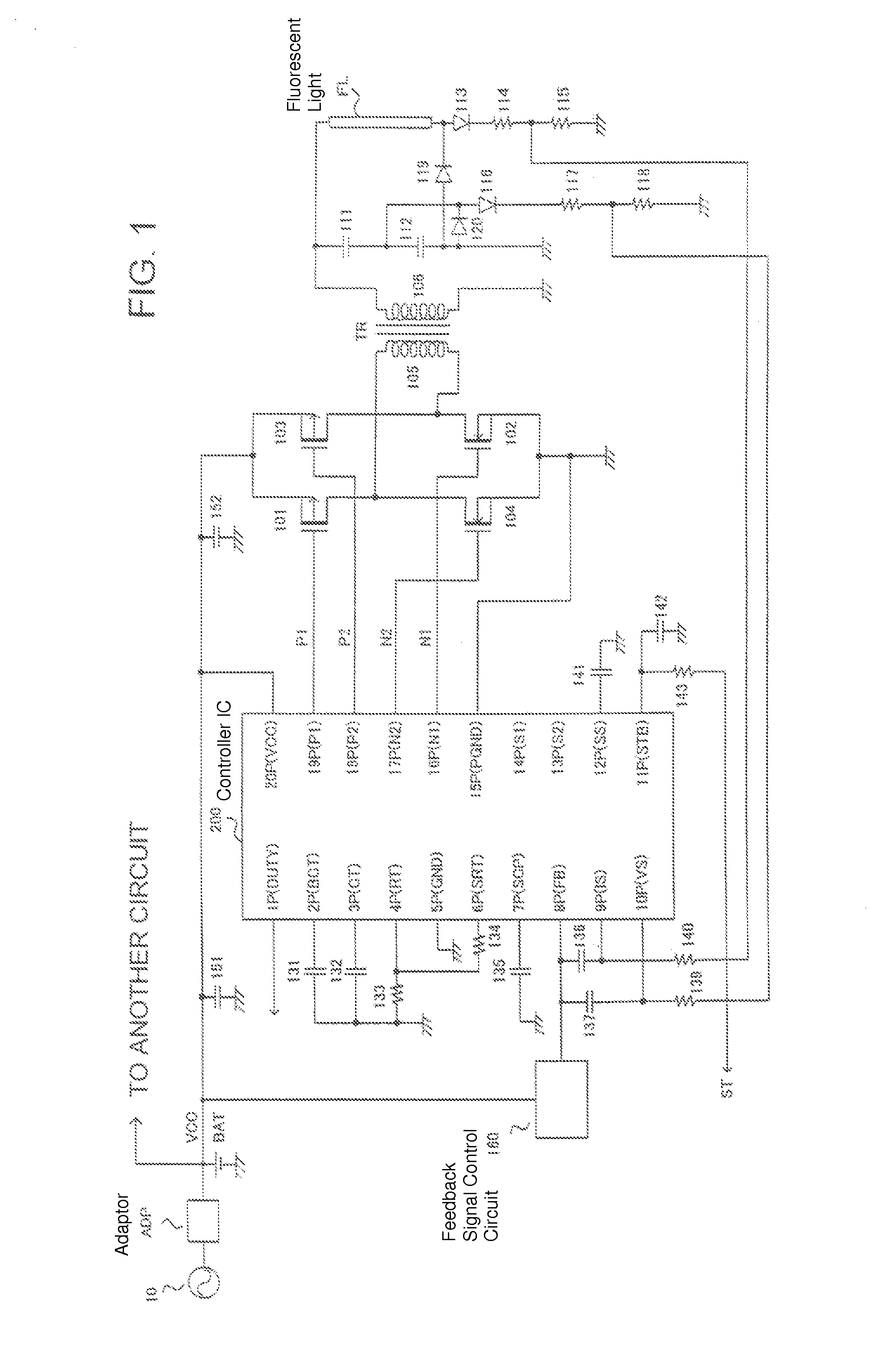
[0037]Referring to the accompanying drawings, the invention will now be described in detail by way of example with reference to an inverter for generating from a DC power supply an AC voltage to drive a load, a controller IC therefor, and an electronic apparatus utilizing the inverter.

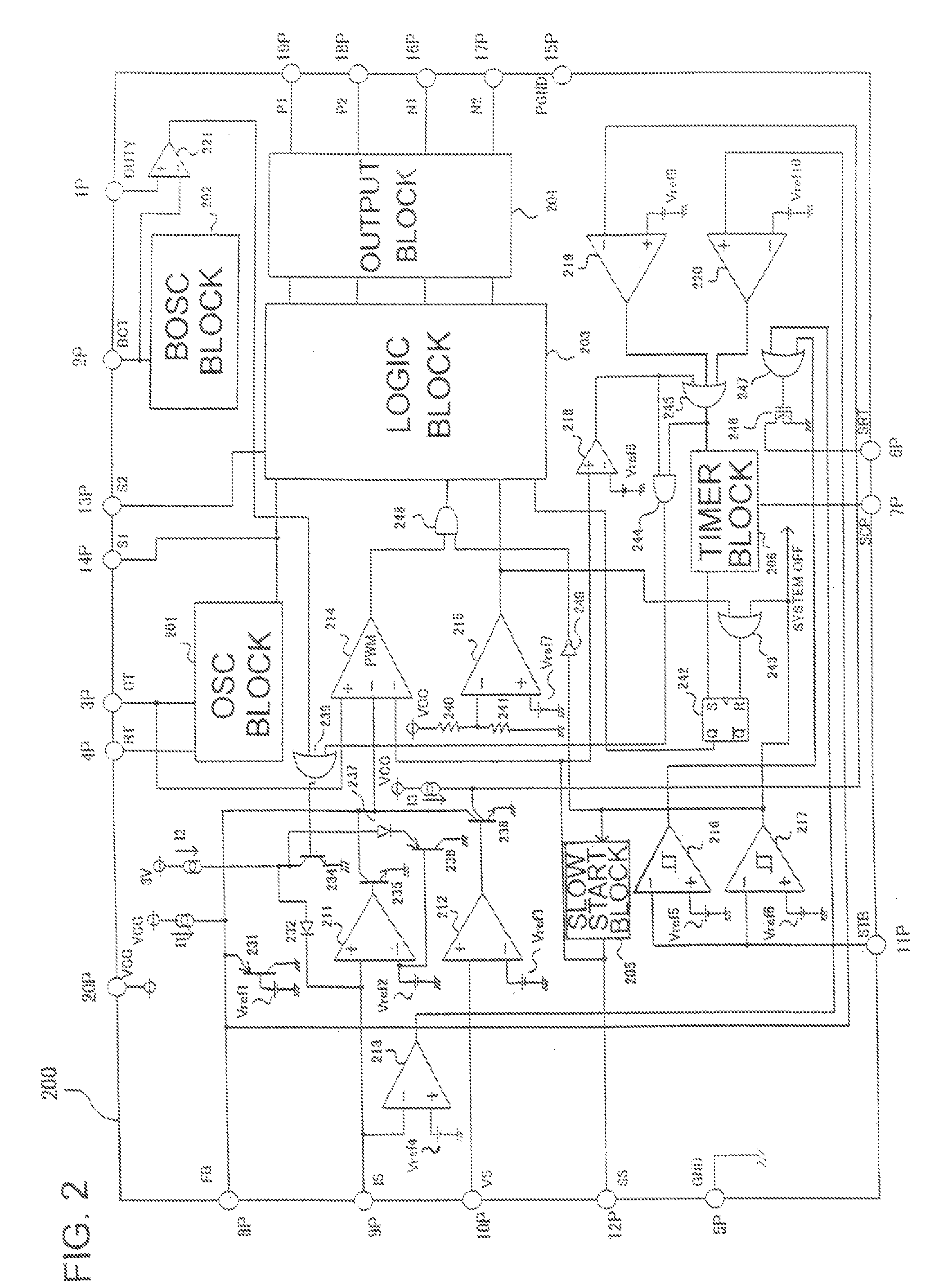
[0038]Referring to FIG. 1, there is shown an over-all arrangement of a first inverter according to the invention that utilizes an insulated transformer and a full-bridge type (or H-bridge type) switching circuit to carry out PWM control. FIG. 2 illustrates the internal structure of a controller IC for controlling the inverter of FIG. 1. The semiconductor switching circuit can be of a half bridge type.

[0039]As shown in FIG. 1, a first switch in the form of a P-type MOSFET (hereinafter referred to as PMOS) 101 and a second switch in the form of an N-type MOSFET (hereinafter referred to as NMOS) 102 together establish a first current path in a first direction through the primary winding 105 of a transform...


PUM


Abstract

An inverter controls the power supplied to a load such as a CCFL connected to a secondary winding of a transformer by means of pulse width modulation (PWM) control of the switches of a semiconductor switching circuit connected to the primary winding of the transformer. The current and voltage supplied to the load are fed back to the inverter in the form of a current error signal and a voltage error signal, respectively, from which a feedback signal is formed in accordance with the magnitudes of these signals. Thus, when the DC supply voltage of a DC power supply sharply rises, the inverter changes the feedback signal directly, that is, without waiting for the changes to occur in the load current and load voltage, so as to reduce the power supplied to the load. Thus, over-current and resultant viewer's discomfort is suppressed. Sudden shut down of the inverter are also prevented from occurring.

Description

TECHNICAL FIELD[0001]This invention relates to a DC-AC converter (hereinafter referred to as inverter) for generating an alternating voltage to drive a load from a DC power supply such as an adapter of an electric apparatus and a battery. The invention also relates to a controller for the DC-AC converter and an electronic apparatus utilizing the inverter.BACKGROUND ART[0002]Cold cathode fluorescent lights (CCFLs) have been increasingly used as a back light source of a liquid crystal display (LCD) for use in, for example, a monitor of a notebook PC, LCD TV set, and car navigation system. Such a CCFL has substantially the same high efficiency and a long life as a usual hot cathode fluorescent light, without using a filament of a hot cathode fluorescent light.[0003]In order to start up and operate the CCFL, high AC voltages are required. For example, a startup voltage of about 1000 V and an operating voltage of about 600 V (in rms value) are required. (Voltages will be hereinafter give...

Claims


Application Information

Patent Timeline
Patent Type & Authority Patents(United States)
IPC IPC(8): H02M7/537G09G3/20G09G3/22H02M1/00
CPCH02M3/3378H05B41/2828H05B41/2853H02M1/32H02M2001/0022Y02B20/186H02M2001/0025H02M1/0022H02M1/0025Y02B20/00H02M7/48H02M7/525
Inventor FUKUMOTO, KENICHI
Owner ROHM CO LTD
Learn More