
LED light structure and combination device thereof

a technology of led light and combination device, which is applied in the direction of coupling device connection, lighting support device, lighting and heating apparatus, etc., can solve the problems of increasing the cost of the general heat sink device, increasing the load on consumers, and increasing the price of aluminum substrate soldered by the conventional led. , to achieve the effect of simple structure, high heat sinking efficiency and simple structur

Active Publication Date: 2009-09-29
LI HONG TECHNOLOGICAL
View PDF2 Cites 5 Cited by
  • Summary
  • Abstract
  • Description
  • Claims
  • Application Information

AI Technical Summary

Benefits of technology

"The present invention provides an LED light structure with combination device that can be easily fixed and combined on a heat sinking base. The LED light has a protruding portion mounted at one side with a matching thread, and the fixing base has a through trough with a matching thread. The LED light and fixing base can be tightly embedded together, achieving direct combination. The combination device helps to effectively reduce the media between the heat radiator and the heat sinker, simplifying the structure and reducing manufacturing costs."

Problems solved by technology

1. As heat dispersing, the heat of most conventional LEDs is dispersed through the aluminum substrate transmitting the heat to the heat sink fin, but the more the media used for transmitting the heat, the less the heat dispersed by the heat sink fin. This is because most heat is absorbed by the media passed by the heat and not dispersed.
2. The price of the aluminum substrate soldered by the conventional LED becomes higher and higher, which not only obviously will lift up the cost of the general heat sink device, but will also increase the consumer's loading.

Method used


Image

  • LED light structure and combination device thereof
  • LED light structure and combination device thereof
  • LED light structure and combination device thereof

Examples


Embodiment Construction

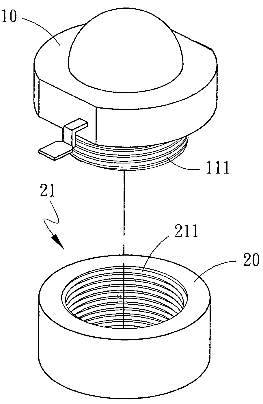
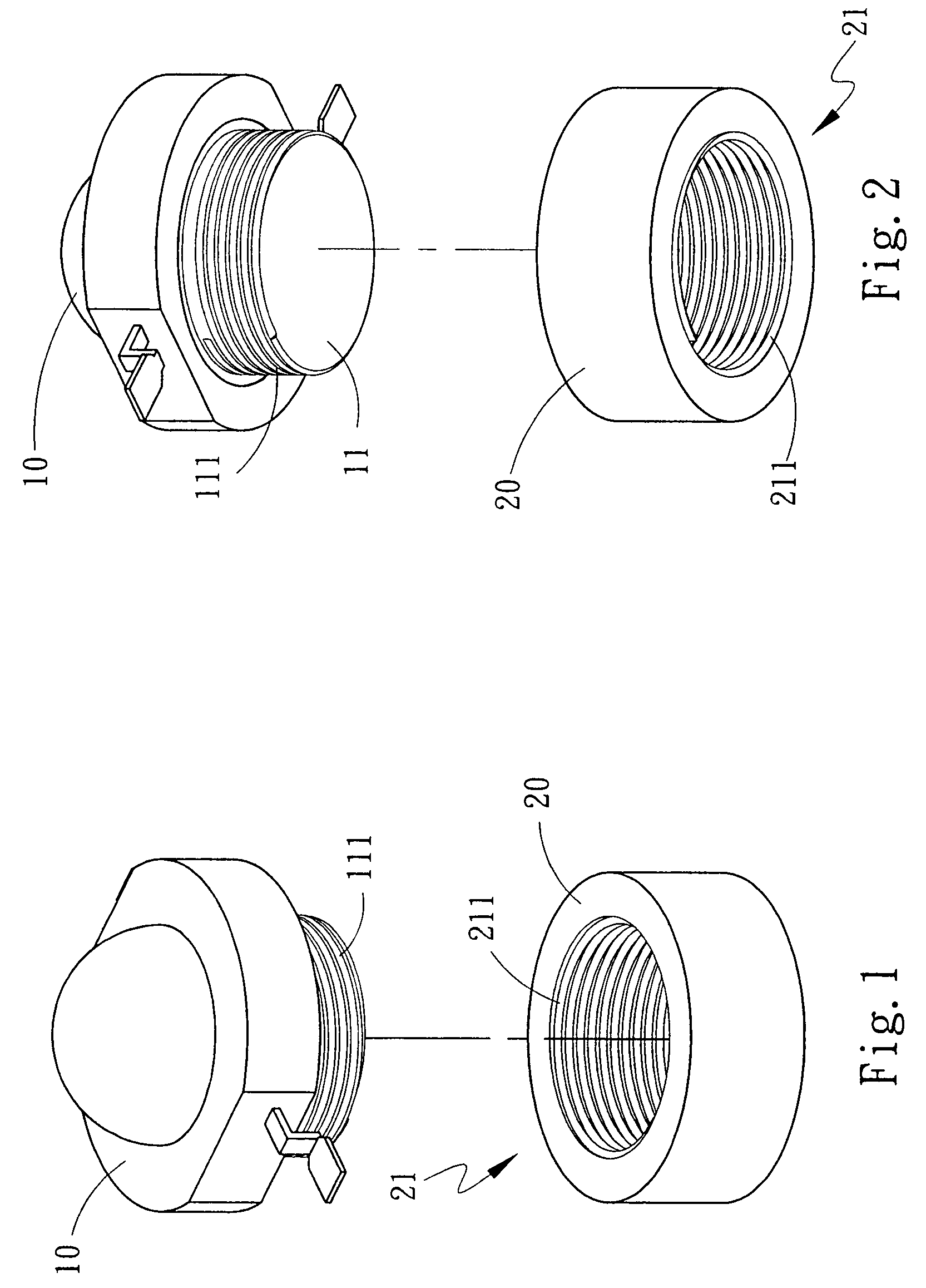
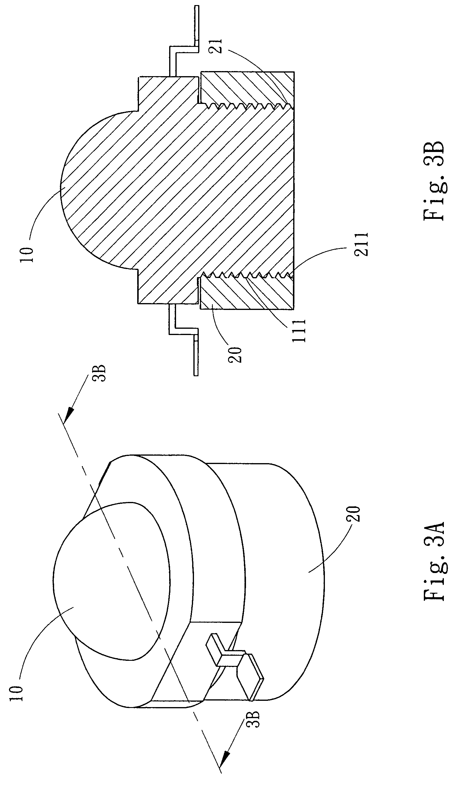
[0041]Please refer to FIGS. 1, 2, 3A and 3B. A LED light structure with a combination device at least includes plural LED lights 10 and plural fixing bases 20. The LED light 10 has a protruding portion 11 mounted at one side thereof, and the protruding portion 11 has a thread 111 mounted thereon for fixing with the fixing base 20. The fixing base 20 is a metal base with high heat sinking efficiency, and the fixing base 20 has a through trough 21 with a thread 211, which matches to the thread 111 on the protruding portion 11 of the LED light 10. According to different demands, the through trough 21 of the fixing base 20 also can be implemented as a blind hole, as shown in FIG. 3C, and the fixing base 20 also can be made of other metals with high heat sinking efficiency, such as copper, aluminum. Besides, as shown in FIG. 3D, the thread 11a on the protruding portion 11 of the LED light 10 also can be implemented as internal thread, and correspondingly, the through trough 21 of the fix...


PUM


Abstract

An LED light structure with combination device has at least including plural LED lights and plural fixing bases, wherein the LED light having a protruding portion mounted at one side thereof and the protruding portion having a thread mounted thereon for fixing with the fixing base which is a metal base with high heat sinking efficiency, and the fixing base has a through trough with a thread mounted thereinside, which is matching to the thread on the protruding portion of the LED light, so as to screw with the protruding portion of the LED light in a tight matching. Here, the protruding portion of the LED light can be a T shaped track and the fixing base can correspondingly have a T shaped trough matching to the shape of the protruding portion of the LED light, so that the LED light and the fixing base can be tightly embedded together.

Description

FIELD OF THE INVENTION[0001]The present invention is related to an LED light structure with combination device, and more particularly to an LED light which can be directly fixed on a base which can disperse the heat and combine with other heat dispersing body.BACKGROUND OF THE INVENTION[0002]Conventionally, when disposing LED, the LED is soldered on an aluminum substrate first, and then, the aluminum substrate is attached to a heat sink fin. However, this conventional method has the disadvantages that:[0003]1. As heat dispersing, the heat of most conventional LEDs is dispersed through the aluminum substrate transmitting the heat to the heat sink fin, but the more the media used for transmitting the heat, the less the heat dispersed by the heat sink fin. This is because most heat is absorbed by the media passed by the heat and not dispersed.[0004]2. The price of the aluminum substrate soldered by the conventional LED becomes higher and higher, which not only obviously will lift up th...

Claims


Application Information

Patent Timeline
Patent Type & Authority Patents(United States)
IPC IPC(8): H01R33/00F21V21/00
CPCF21V29/004F21V29/2212F21V19/0015F21V29/89F21V29/73F21V29/74F21Y2101/02H01L33/486F21V29/006Y10T428/24587H01L2924/0002H01L2924/00F21Y2115/10F21V29/51
Inventor CHANG, KUN-JUNGJUAN, CHIANG-YUANLIN, KUO-CHUN
Owner LI HONG TECHNOLOGICAL
Learn More