
Thermoplastic belt connector

a technology of thermoplastic belts and connectors, which is applied in the direction of transportation and packaging, mechanical equipment, other domestic objects, etc., can solve the problems of food particles becoming lodged in the joints affecting the service life of the interconnection links, and /b>inconvenient to clean the belts

Active Publication Date: 2009-09-29
LAITRAM LLC
View PDF8 Cites 17 Cited by
  • Summary
  • Abstract
  • Description
  • Claims
  • Application Information

AI Technical Summary

Benefits of technology

Enables easy removal and reinstallation of the belt without disassembling the conveyor frame, minimizing belt damage and maintaining hygiene standards by allowing the belt to be taken off for cleaning and maintenance without destroying it.

Problems solved by technology

One of the problems with such belts is that food particles can become lodged in the joints of the interconnecting links.
Consequently, cleaning the belts can be difficult and may require removing the belt from the conveyor system for special cleaning operations.
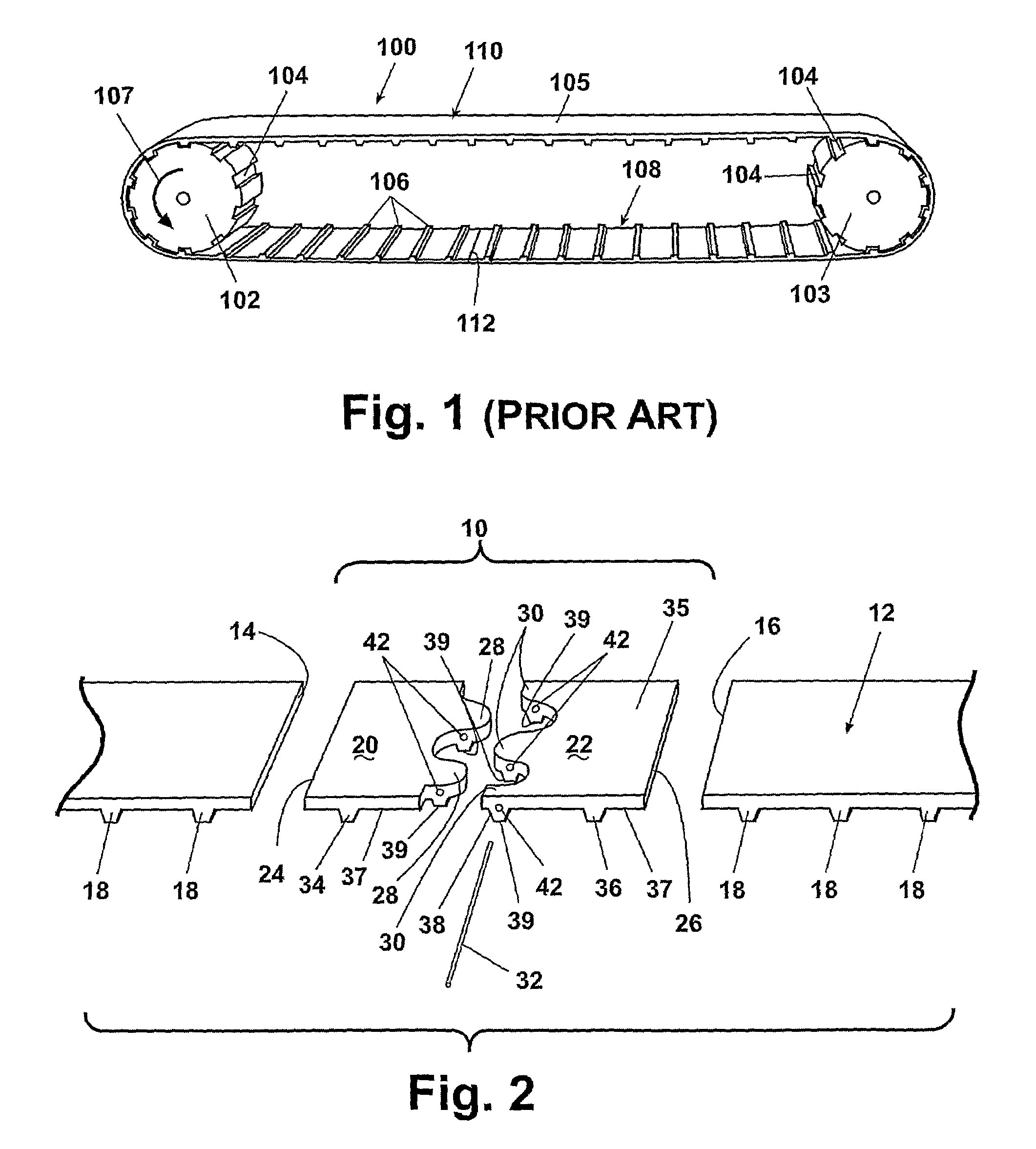
Removing the endless belt 100 of FIG. 1 is an inconvenience, normally requiring disassembly of the conveyor frame, movement of the sprockets, and possibly destruction of the belt (or at least cutting the belt to be re-seamed later).

Method used


Image

  • Thermoplastic belt connector
  • Thermoplastic belt connector
  • Thermoplastic belt connector

Examples


second embodiment

[0027]Turning now to FIG. 6, a belt connector 50 according to the invention provides a solution to minimize the effect of the discontinuity between the knuckles. This embodiment is in most salient respects identical to the previous embodiment, except for the addition of a tooth, a second pin, and the size of the knuckles. Consequently, like complements will bear like numerals with respect to the earlier embodiment.

[0028]The belt connector 50 is injection molded with four teeth, the two outside teeth 34, 36, and two inside teeth 52, 54, all spaced from each other the same pitch as the teeth 18 on the belt 12 to which the belt connector is attached. Each inside tooth 52, 54 is molded with the hole 42 through it, sized to receive the pin 32. A sinusoidal cut 56 extends from one side of the tooth 52 to the other side of the tooth 54 across the recess 37 between them, forming two leaves 58, 60. Each leaf 58, 60 has respective knuckles 62, 64, and each knuckle will have a portion of two o...

first embodiment

[0029]Each leaf 58, 60 is butt welded or otherwise secured by conventional means to the respective end 14, 16 to form respective seams 44, 46. A pin 32 is then inserted through the holes 42 in the respective portions of the inner teeth 52, 54 to secure the respective knuckles 62, 64 to each other. As before, each pin 32 is a wire, coated or covered with a friction enhancing coating to retain the pin within the holes. Alternatively, the pin 32 can be fixed by other means such as simply bending the ends at an angle, or securing removable fasteners to the ends. It will be apparent that with two connection points for each knuckle 62, 64, the knuckles will not rotate about either pin so as to form the kind of discontinuity that appears in the Rather, each knuckle 62, 64 will be urged by the tension of the belt 12 and the engagement of the teeth 52, 54 with the sprocket to bend around the sprocket, thereby minimizing the discontinuity otherwise caused by the sinusoidal cut 56. As with th...


PUM

PropertyMeasurementUnit
widthaaaaaaaaaa
thermoplasticaaaaaaaaaa
tensionaaaaaaaaaa

Abstract

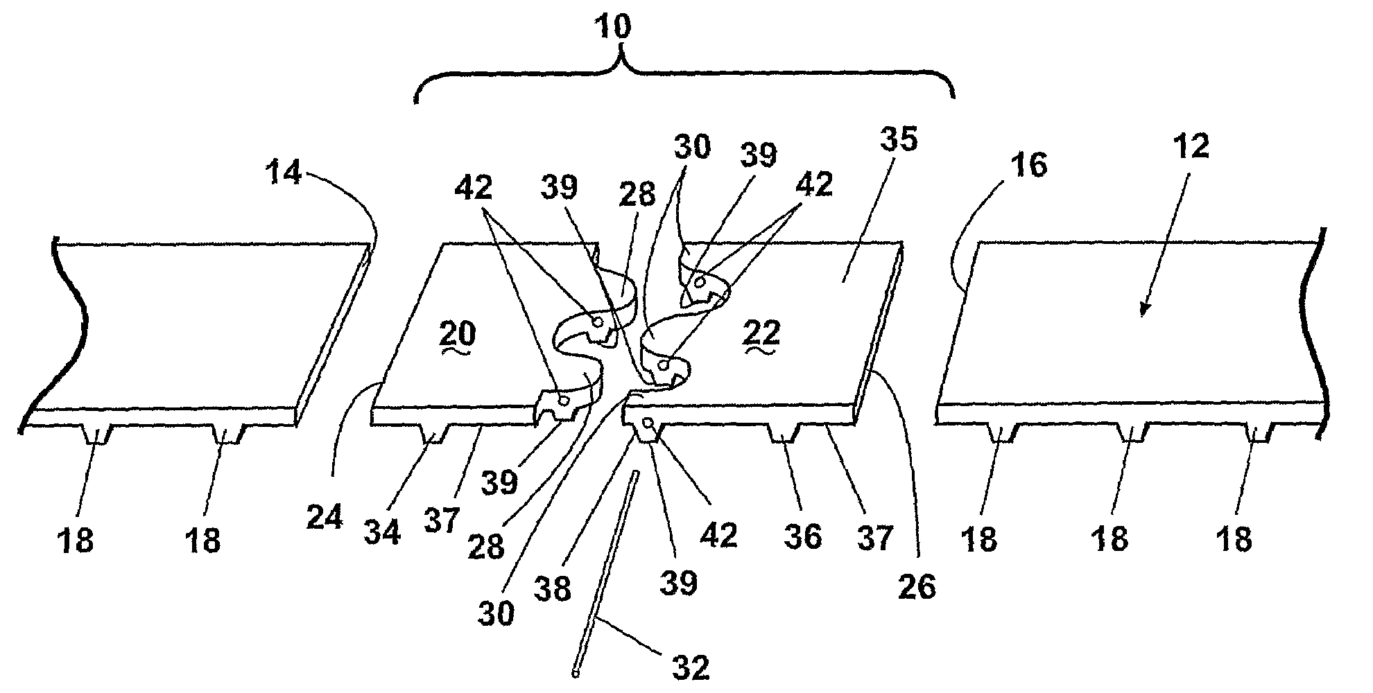
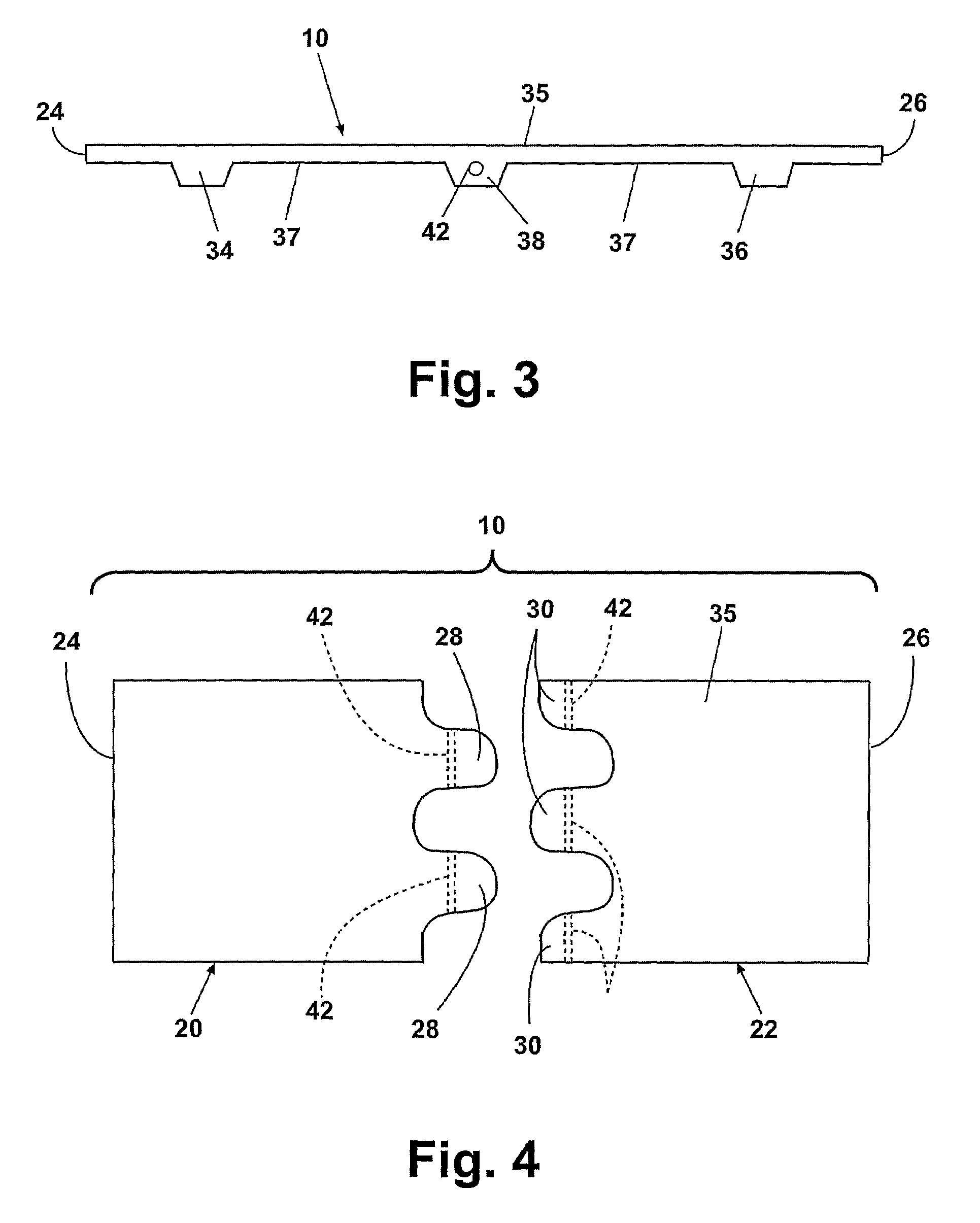
A thermoplastic toothed belt connector (10, 50) for making an endless belt (12) has two leaves (20, 22, 58, 60), adapted to be hingedly connected to each other by knuckles (28, 30, 60, 62) along one or more teeth (38, 52, 54). Each knuckle (28, 30, 60, 62) has a hole (42, 72) extending through tooth portions (39) so that when the holes (42, 72) are in the registry, a pin (32, 74) can be extended through the holes (42, 72) to form the hinge at the teeth (38, 52, 54). The leaves (20, 22, 58, 60) can be adjoined to the ends of a thermoplastic belt (12) to make the belt endless.

Description

CROSS-REFERENCE TO RELATED APPLICATIONS[0001]This application claims priority on International Application No. PCT / US2005 / 039744, filed Nov. 2, 2005, which claims the benefit of U.S. Provisional Patent Application No. 60 / 522,756, filed Nov. 3, 2004, both of which are incorporated herein in their entirety.BACKGROUND OF THE INVENTION[0002]1. Field of the Invention[0003]This invention relates to endless belts for conveyors and, more particularly, to connectors for making thermoplastic endless belts to be driven by sprockets.[0004]2. Description of the Related Art[0005]Low tension, direct drive conveyor belts are typically used in situations where hygiene and cleanliness are critically important. For example, in food processing plants such as those that process meat products for human consumption, low tension, direct drive belt conveyors are used to transport items. Sanitation is critically important and, therefore, the endless belts used in such conveyors are conventionally made of mat...

Claims


Application Information

Patent Timeline
Patent Type & Authority Patents(United States)
IPC IPC(8): B65G15/32
CPCB29C65/564B29C66/1142B29C66/221B29C66/4322B29C66/5241F16G3/02F16G1/14F16G1/28B29C66/4324Y10T24/162B29L2031/7092B29L2016/00
Inventor MOL, EDWARD T.HONEYCUTT, JAMES
Owner LAITRAM LLC
Learn More