
Plasma reformer and internal combustion engine system having the same

a technology of reformer and internal combustion engine, which is applied in the direction of liquid chemical process, liquid gas reaction of thin film type, gas-gas reaction process, etc., can solve the problems of high cost of method, unpopularity, and insufficient technology of method, so as to improve the reforming effect of gas containing hydrogen, reduce plasma power, and increase the lifetime of electrode material

Active Publication Date: 2009-09-22
IND TECH RES INST
View PDF9 Cites 9 Cited by
  • Summary
  • Abstract
  • Description
  • Claims
  • Application Information

AI Technical Summary

Benefits of technology

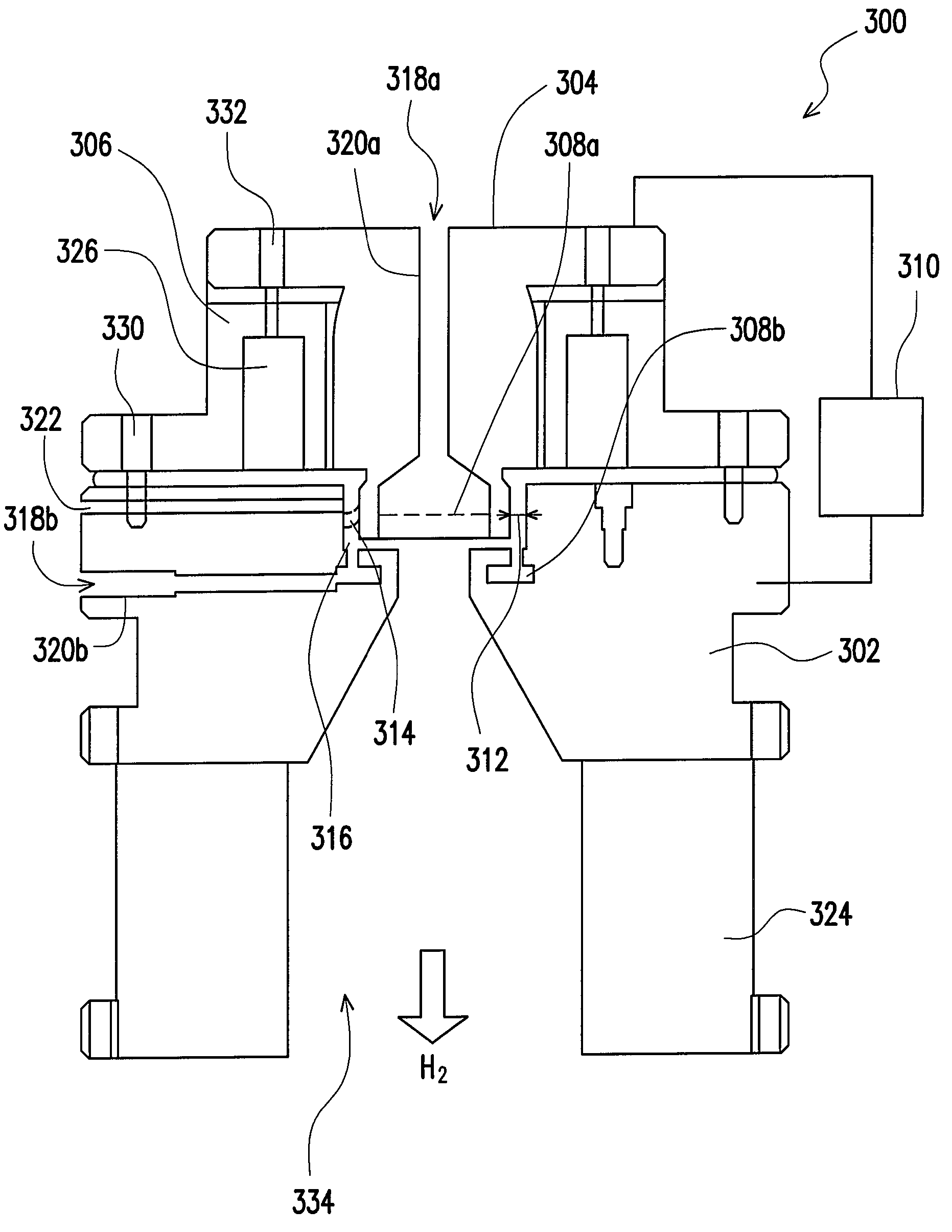
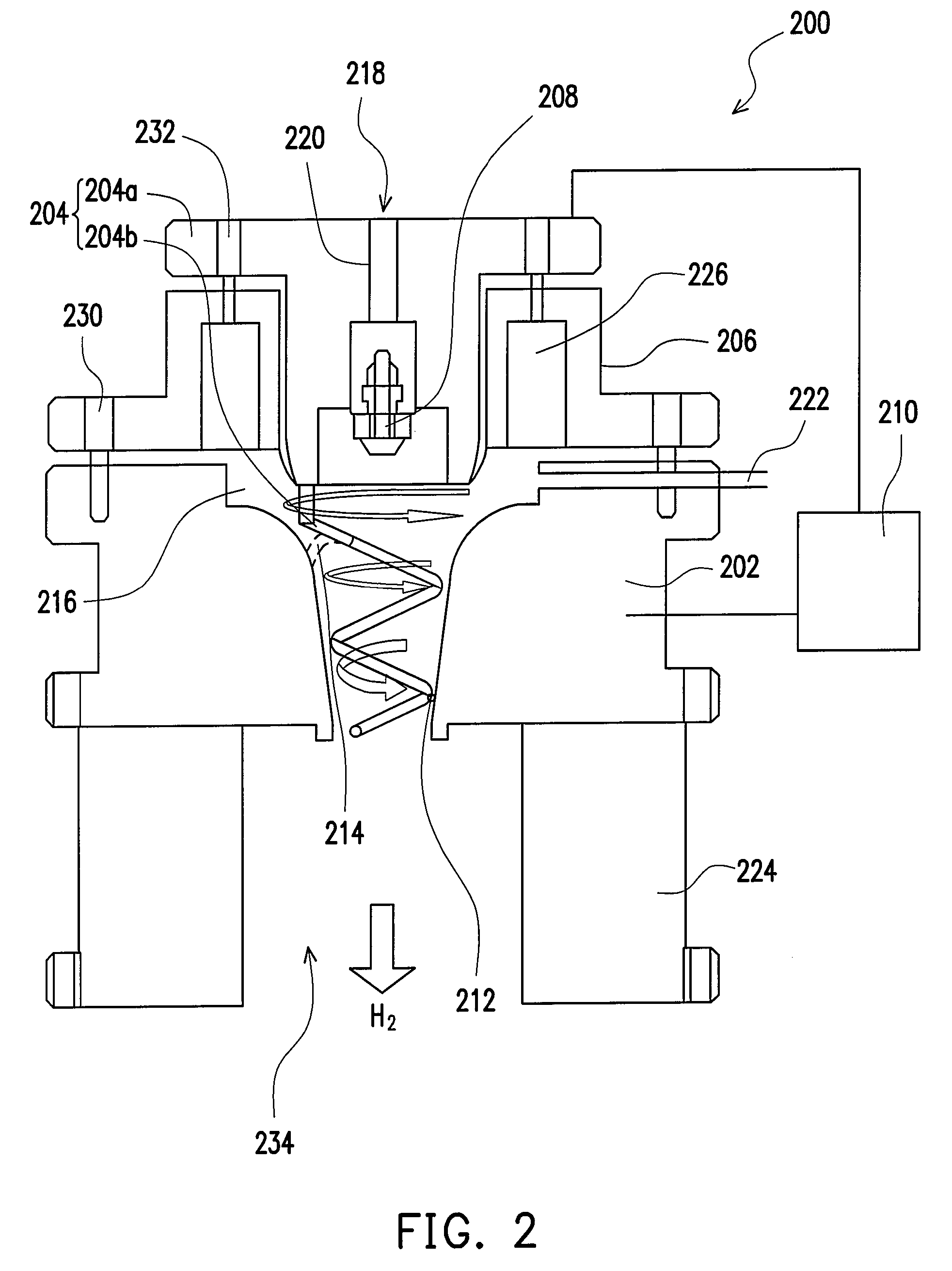
The present invention provides a plasma reformer that decreases plasma power through high voltage, low current output to increase the lifetime of electrodes material to produce a better reforming effect of gas containing hydrogen. The plasma reformer includes a first electrode, a second electrode, an insulating member, an atomizing device, a power supply, and a discharge gap. The plasma reformer also includes a vortex gas flow route, a tangential gas guiding-pipe, and a product gas output. The plasma reformer can enhance the combustion efficiency of the engine and decrease air pollution when used in an internal-combustion engine system. The plasma reformer can also be assembled with an internal-combustion engine system to support hydrogen combustion and decrease air pollution.

Problems solved by technology

However, the technology of the method is not ripe, and the cost of the method is high so that the method is not popular.
The application of the fuel cell is embarrassed since the infrastructure for supplying hydrogen is not ripe.
Furthermore, the hydrogen has a low volumetric energy density such that compared with the hydrocarbon fuel, the hydrogen is difficult to be stored and carried.
However, the conventional DC arc plasma fuel reformer lost biggish energy, the electric power is generally larger than real need.
Therefore, these methods cannot effectively solve the problem that the lifetime of the electrodes is short.

Method used


Image

  • Plasma reformer and internal combustion engine system having the same
  • Plasma reformer and internal combustion engine system having the same
  • Plasma reformer and internal combustion engine system having the same

Examples


Embodiment Construction

[0025]Reference will now be made in detail to the present preferred embodiments of the invention, examples of which are illustrated in the accompanying drawings. Wherever possible, the same reference numbers are used in the drawings and the description to refer to the same or like parts.

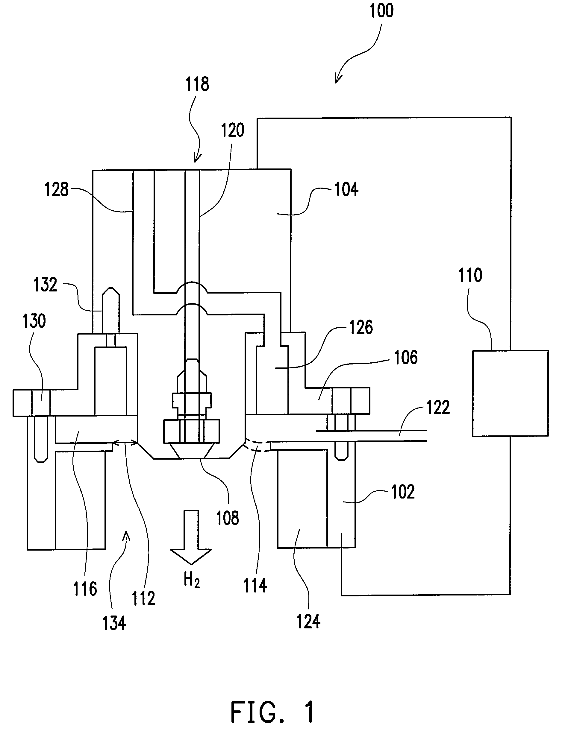
[0026]A plasma reformer of the present invention is a device, which uses a gas to drive the standing arc discharge to accelerate a reforming between hydrocarbon and water (or gas containing oxygen) to produce a hydrogen-rich gas.

[0027]FIG. 1 is a schematic view of a plasma reformer in accordance with a first preferred embodiment of the present invention.

[0028]Referring to FIG. 1, the plasma reformer 100 includes a first electrode 102, a second electrode 104, an insulating member 106, an atomizing device 108 and a power supply 110.

[0029]The first electrode 102 is made of an electric material, for example. The first electrode 102 includes a hollow disk conductor, a hollow tubular conductor having a sym...


PUM


Abstract

A plasma reformer includes a first electrode, a second electrode, an insulating member, an atomizing device and a power supply. A discharge gap is defined between the first electrode and the second electrode. The insulating member is arranged between the first electrode and the second electrode to insulating the first electrode and the second electrode, and a vortex gas flow route is formed between the insulating member and the first electrode, the second electrode. The second electrode penetrates the insulating member. The atomizing device is arranged on the first electrode and / or the second electrode. The power supply is connected with the first electrode and the second electrode.

Description

CROSS-REFERENCE TO RELATED APPLICATION[0001]This application claims the priority benefit of Taiwan application serial no. 95148407, filed on Dec. 22, 2006. All disclosure of the Taiwan application is incorporated herein by reference.BACKGROUND OF THE INVENTION[0002]1. Field of the Invention[0003]The present invention relates to a fuel reforming device, and more particularly to a plasma reformer and an internal-combustion engine system having the same.[0004]2. Description of the Related Art[0005]With the advancement of the industry, the consumptions of the conventional energy sources, such as coal, oil, and natural gas, etc., are increased duratively. Since those natural energy sources have limited reserves, new energy sources must be developed to replace the conventional energy sources. A fuel cell is an important new power device with practical values.[0006]Simply speaking, the fuel cell generates electrical power via a redox reaction. Compared with the other modes of generating el...

Claims


Application Information

Patent Timeline
Patent Type & Authority Patents(United States)
IPC IPC(8): F02M29/00F02B51/04F02M57/06
CPCB01J19/088C01B3/342C01B3/366F02B51/04F02M25/0228F02M25/12Y02T10/126B01J2219/083B01J2219/0869B01J2219/0883B01J2219/0884B01J2219/0892C01B2203/0216C01B2203/0222C01B2203/0233C01B2203/0238C01B2203/0244C01B2203/0255C01B2203/0261C01B2203/06C01B2203/066C01B2203/0861C01B2203/1235C01B2203/142Y02T10/121B01J2219/0809Y02T10/12Y02P20/141
Inventor SHIH, MING-SHIANNLIN, HENG-JUHSIAO, CHING-SUNGHUANG, TING-WEI
Owner IND TECH RES INST
Learn More