
Video converting device and method for digital TV

a technology of converting device and digital tv, which is applied in the field of digital tv, can solve the problems that digital tv in the related art cannot provide a pleasant viewing experience to a user, and requires a certain amount of time, and achieve the effect of beautiful screen display

Inactive Publication Date: 2009-09-15
LG ELECTRONICS INC
View PDF34 Cites 26 Cited by
  • Summary
  • Abstract
  • Description
  • Claims
  • Application Information

AI Technical Summary

Benefits of technology

The present invention provides a video converting device and method for a digital TV that can efficiently process video for various conversions. The device includes a memory for video decoding and display, a video decoder, a video and conversion information detector, a display processor, a video signal processing controller, a pattern generator, and a video selector. The device can detect the type of conversion, the input and output video formats, and the position of the memory to control the video decoding, conversion, and display. The invention also allows for the repeated display of a previous video for a predetermined time period during which the conversion is being processed. The invention provides a solution for video conversions that are dissimilar and require memory remapping. The control signal output from the video signal processing controller to the display processor blanks or freezes the converted video signal only when there is a change in the type of conversion being performed.

Problems solved by technology

However, the digital TV in the related art requires relatively a certain amount of time from the reception to the display of an input signal when there is a change of channel.
However, a digital TV in the related art simply processes and displays, even a noise, if a video signal is not contained in the input signal.
As a result, the digital TV in the related art cannot provide a pleasant viewing experience to a user.

Method used


Image

  • Video converting device and method for digital TV
  • Video converting device and method for digital TV
  • Video converting device and method for digital TV

Examples


Embodiment Construction

[0050]Reference will now be made in detail to various embodiments of the present invention, examples of which are illustrated in the accompanying drawings.

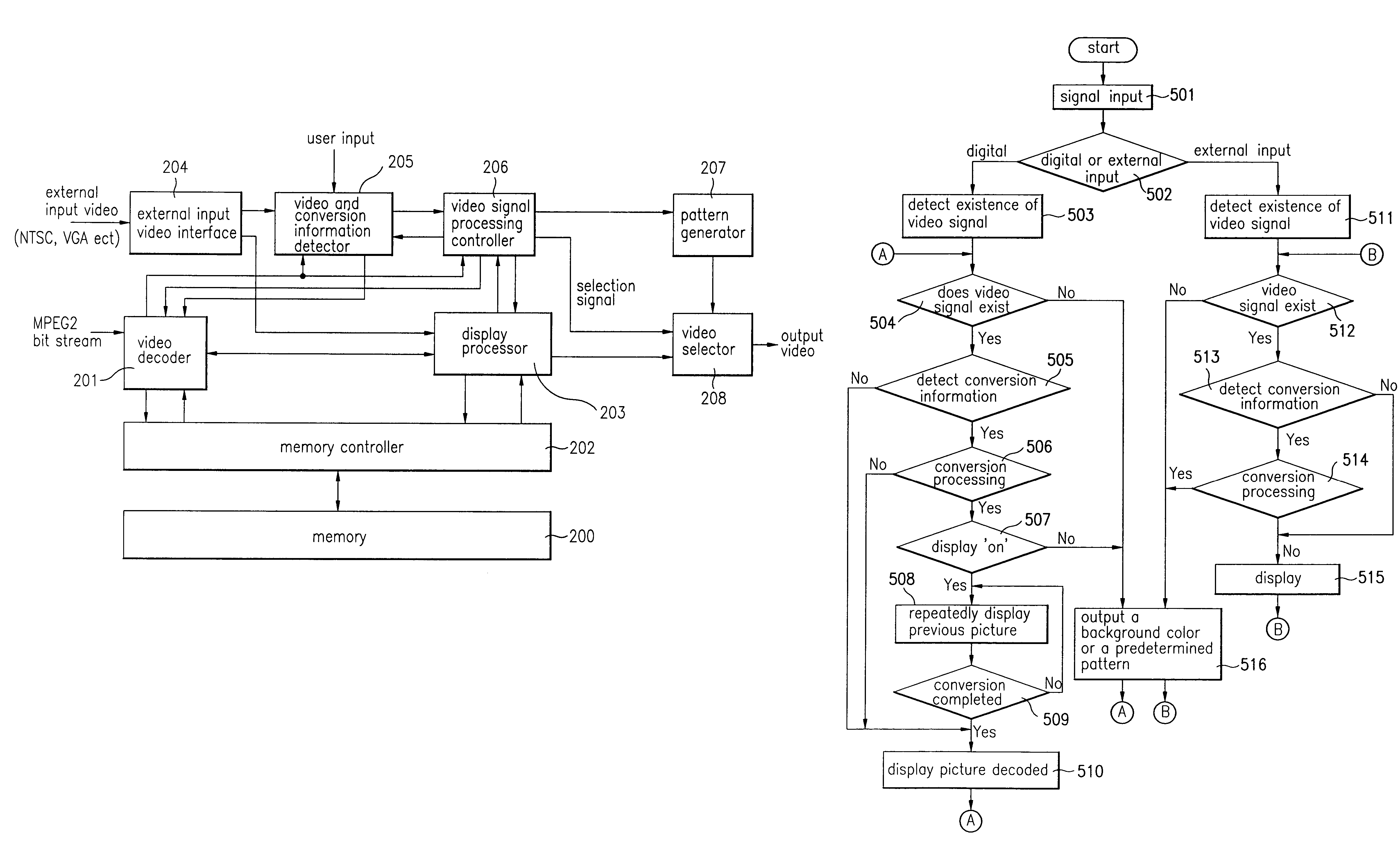
[0051]FIG. 4 is a block diagram of a video converting device for a digital TV according to the present invention. In an exemplary embodiment, the digital TV employs an external memory 200 which includes a buffer for temporarily storing a bit stream and a frame memory. However, any other memory including an internal memory may be implemented rather than the external memory 200.

[0052]Referring to FIG. 4, the video converting device according to an exemplary embodiment of the present invention includes a video decoder 201 which reads and decodes a bit stream stored in the external memory 200, and stores the decoded bit stream back in the external memory 200; a display processor 203 which reads data from the memory 200 in accordance with conversion commands in order to process the corresponding conversions, thereby storing the convert...


PUM


Abstract

A video converting device and method for a digital TV is disclosed. The present invention is capable of detecting whether a conversion is being processed and displaying a previous video or a predetermined pattern for a predetermined time during which the conversion is being processed. If there is no video signal, the present invention displays a predetermined pattern, thereby outputting a pleasant screen to a user. Also, the present invention reduces the conversion time by structuring the bit streams into a GOP.

Description

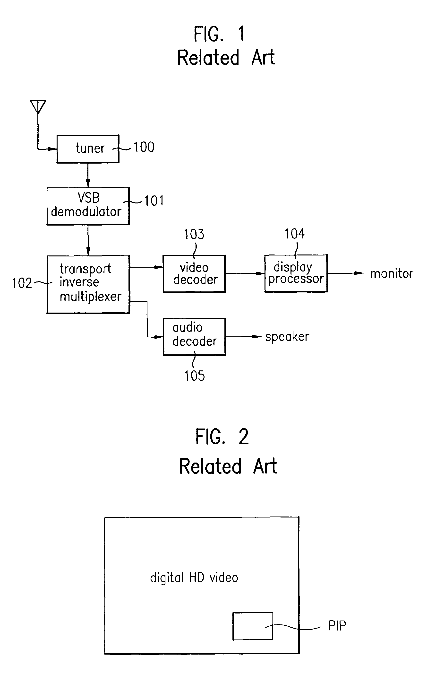
[0001]This application is a Continuation-In-Part of application Ser. No. 09 / 566,630, filed on May 8, 2000 now abandoned, the entire contents of which are hereby incorporated by reference and for which priority is claimed under 35 U.S.C. § 120. This application also claims foreign priority benefit of Korean Application Nos. 1999-16469 and 1999-16470 filed respectively on May 8, 1999, the entire contents of which are hereby incorporated by reference.BACKGROUND OF THE INVENTION[0002]1. Field of the Invention[0003]The present invention relates to a digital TV, and more particularly, to a video converting device and method for a digital TV.[0004]2. Discussion of Related Art[0005]Generally, a digital TV provides an image of a higher quality to a viewer when compared with an analog TV. Therefore, as the interest in digital TVs rise, the technology to compress and transmit video data to a digital TV receiver has been rapidly developing.[0006]FIG. 1 is a block diagram of a typical digital TV...

Claims


Application Information

Patent Timeline
Patent Type & Authority Patents(United States)
IPC IPC(8): H04N7/01H04N11/20H04N5/44H04N5/46H04N5/50
CPCH04N5/4401H04N5/46H04N5/50H04N21/4858H04N21/435H04N21/4384H04N21/44016H04N21/482H04N21/4307H04N21/4316H04N21/426H04N21/43072
Inventor CHOI, SEUNG J.
Owner LG ELECTRONICS INC
Learn More