Method and apparatus for absolute optical encoders with reduced sensitivity to scale or disk mounting errors
an absolute optical encoder and scale technology, applied in the field of absolute optical encoders, can solve the problems of inability to accurately detect the position of the object, inability to accurately detect the position,
- Summary
- Abstract
- Description
- Claims
- Application Information
AI Technical Summary
Benefits of technology
Problems solved by technology
Method used
Image
Examples
first embodiment
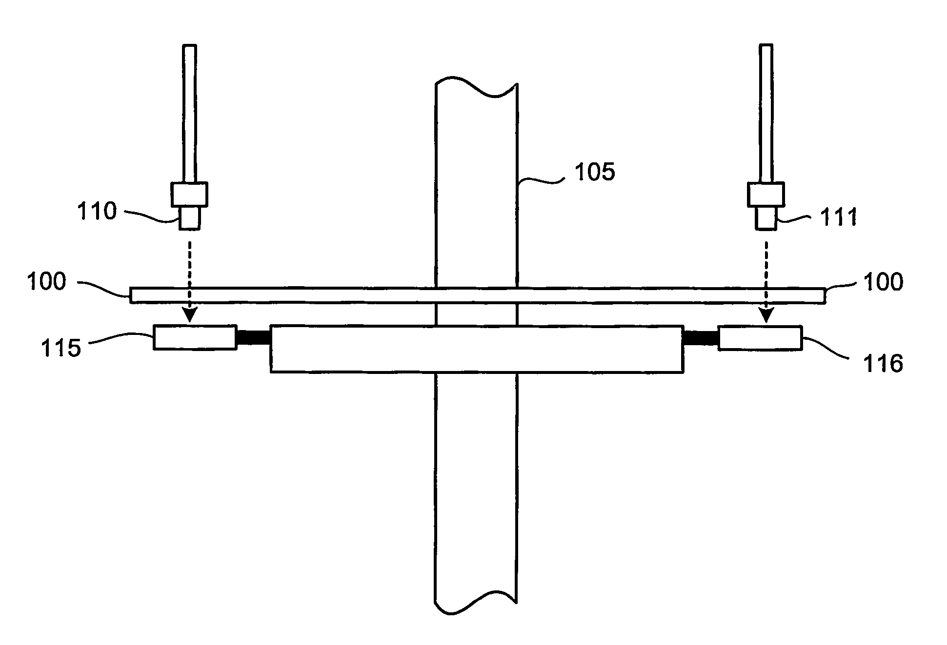
[0026]FIG. 1a depicts a simplified side view illustration of the basic components of a rotary optical encoder operating in accordance with the invention. A disk 100 is mounted on a shaft 105 that rotates about the shaft axis in direct relationship with the item being monitored. The disks used in rotary optical encoders are typically composed of a glass, plastic, ceramic, or metal that have coded markings precisely embedded in a track that encircles the outer portion of the disk. The markings are detected by an arrangement comprising a photoemitter light source 110,111 mounted on one side of the disk 100 and photo detectors 115,116 mounted on the other side of the disk. The disk may be of a construction having an opaque background with transparent markings so that the light passing through the transparent markings is detected. Alternatively, the disk can be transparent with opaque markings, in which case the photo detectors detect the interruption of light by the passing markings.
[00...
second embodiment
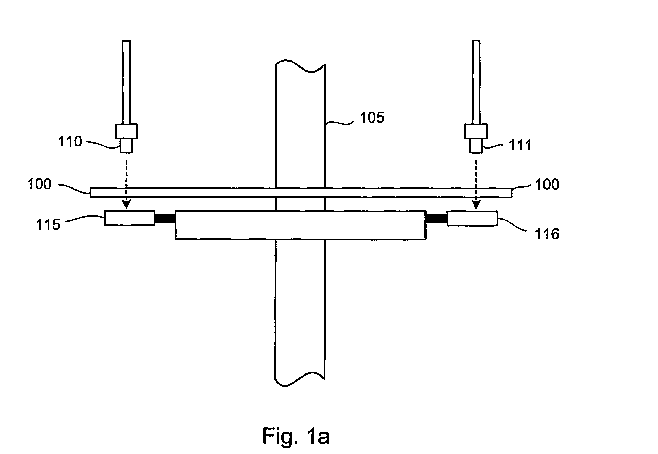
[0028]FIG. 1b depicts a side view of the rotary optical encoder operating in accordance with the invention. The arrangement here is configured so that the photoemitter light source and photo detector (110,115 and 111,116) is proximally located to each other and on the same side of the disk. In fact the laser and the sensor can be incorporated on the same integrated circuit chip, although this is not necessary. In the preferred embodiment, the light source 110,111 is located slightly outside the disk 100 such that the emitted light is reflected by mirror 118,119 through the disk and markings, which are detected by the photo detector 115,116. It should be noted that the invention is not limited to this configuration and that other configurations are possible such as locating both the light source underneath the disk rather than slightly outside of it or conversely locating the sensor slightly outside the disk instead of the light source, for example.
[0029]The photo detectors comprise ...
PUM
 Abstract
Description
Claims
Application Information
 - R&D
- Intellectual Property
- Life Sciences
- Materials
- Tech Scout
- Unparalleled Data Quality
- Higher Quality Content
- 60% Fewer Hallucinations
Browse by: Latest US Patents, China's latest patents, Technical Efficacy Thesaurus, Application Domain, Technology Topic, Popular Technical Reports.
© 2025 PatSnap. All rights reserved.Legal|Privacy policy|Modern Slavery Act Transparency Statement|Sitemap|About US| Contact US: help@patsnap.com


