
Memory, bit-line pre-charge circuit and bit-line pre-charge method

a pre-charge circuit and memory technology, applied in the field of memory, bit-line pre-charge circuit and bit-line pre-charge method, can solve the problems of difficult control of precise start procedure, operation procedure, and difficulty in precisely determining the delay time of the delay circuit, so as to prevent over-charge

Inactive Publication Date: 2009-09-08
MACRONIX INT CO LTD
View PDF4 Cites 3 Cited by
  • Summary
  • Abstract
  • Description
  • Claims
  • Application Information

AI Technical Summary

Benefits of technology

The present invention provides a bit-line pre-charge circuit and method to speed up the pre-charge of the bit line, close the extra pre-charge path early enough, and generate enough voltage margin to prevent the overcharge. The sensing conceptual scheme of memory includes a clamp transistor, an inverter, a bit line, and a memory cell. The pre-charge scheme of memory includes a pre-charge path and a detector and controller circuit. The bit-line pre-charge method is for a plurality of bit-lines in a memory array, wherein each bit-line is coupled to a clamp transistor. The clamp transistor has a sensing voltage thereon, and the bit line has a bit-line voltage thereon. The method includes detecting the sensing voltage, pre-charging the clamp transistor to raise the bit-line voltage when the sensing voltage is at a low level, and stopping pre-charging the clamp transistor when the sensing voltage is at a high level.

Problems solved by technology

It is therefore difficult to control precisely the delay time of the delay circuit 12.
That is to say, it is difficult to control precisely the start procedure, the operation procedure and the close procedure of the extra pre-charge path 11.

Method used


Image

  • Memory, bit-line pre-charge circuit and bit-line pre-charge method
  • Memory, bit-line pre-charge circuit and bit-line pre-charge method
  • Memory, bit-line pre-charge circuit and bit-line pre-charge method

Examples


Embodiment Construction

[0021]The present invention will now be described more specifically with reference to the following embodiments. It is to be noted that the following descriptions of preferred embodiments of this invention are presented herein for the purposes of illustration and description only; it is not intended to be exhaustive or to be limited to the precise form disclosed.

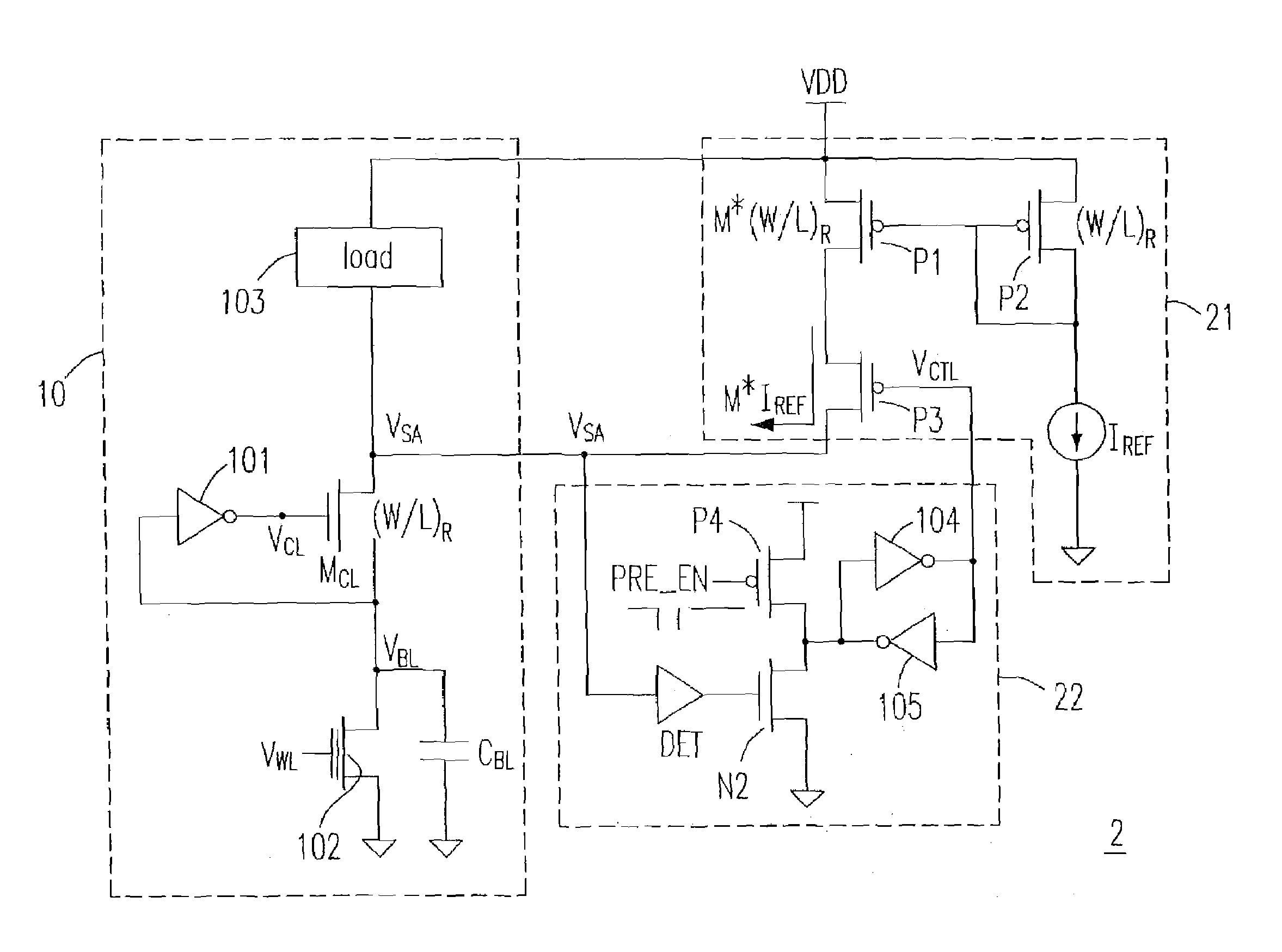
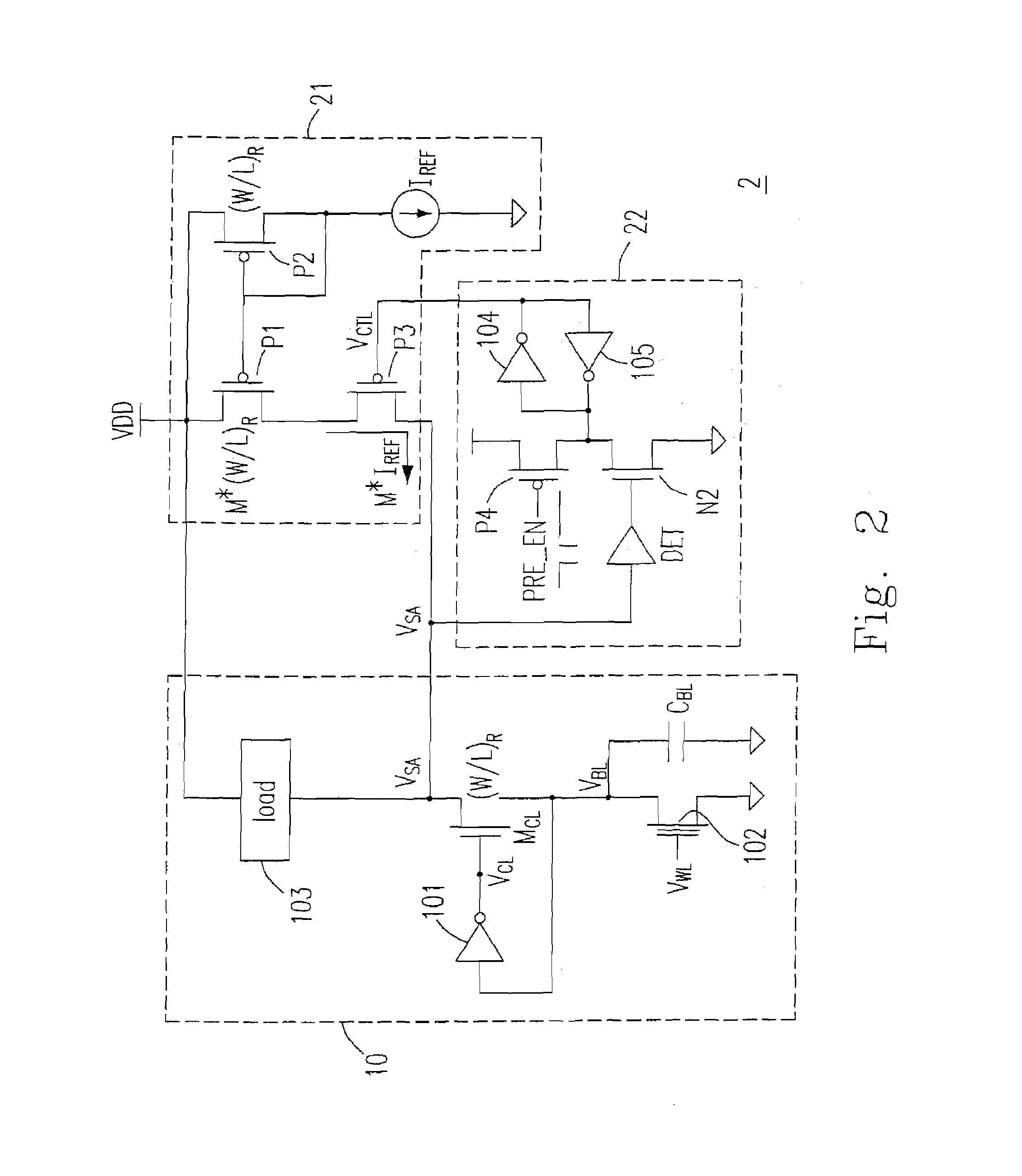
[0022]To solve the above problems, the present invention provides a memory which includes an extra pre-charge path and a detector and controller circuit electrically connected thereto, besides the sensing conceptual scheme 10 including the clamp transistor MCL, the inverter 101 and the bit line.

[0023]Please refer to FIG. 2, which is a circuit diagram showing a memory according to a preferred embodiment of the present invention. In FIG. 2, the circuit configuration of the sensing conceptual scheme 10 is as identical as that shown in FIG. 1. Besides the sensing conceptual scheme 10, the memory 2 further includes a pre-charge p...


PUM


Abstract

A memory is provided. The memory includes a memory cell, a clamp transistor, an inverter, a bit line, a pre-charge path and a detector and controller circuit. The memory is coupled to the clamp transistor. The clamp transistor has a first end, a second end and a control end. The inverter has an input end electrically connected to the second end of the clamp transistor and an output end electrically connected to the control end of the clamp transistor. The bit line is electrically connected to the second end of the clamp transistor and the input end of the inverter and has a bit-line voltage thereon. The pre-charge path is electrically connected to the first end of the clamp transistor through a node having a sensing voltage thereon. The detector and controller circuit is electrically connected to the first end of the clamp transistor and the pre-charge path for detecting the sensing voltage in order to open the pre-charge path to raise the bit-line voltage when the sensing voltage is at a low level and close the pre-charge path when the sensing voltage is at a high level.

Description

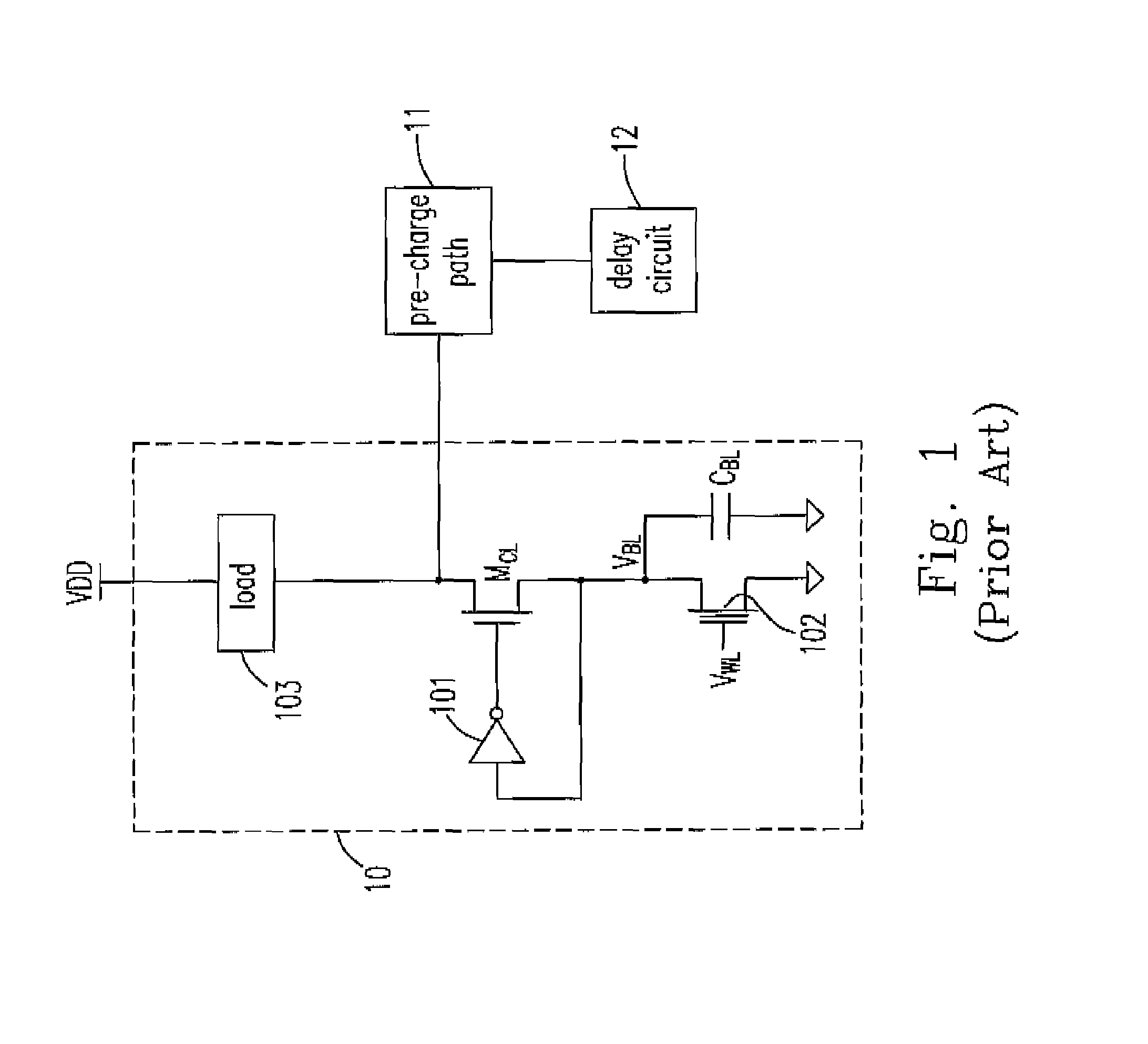
FIELD OF THE INVENTION[0001]The present invention relates to a memory, bit-line pre-charge circuit and bit-line pre-charge method, and more particularly to a memory, bit-line pre-charge circuit and bit-line pre-charge method for bit line voltage in a memory cell.BACKGROUND OF THE INVENTION[0002]Please refer to FIG. 1, which is a circuit diagram showing a sensing conceptual scheme and precharge circuit in a conventional memory array according to the prior art. In FIG. 1, the control circuit of only one cell of a plurality of cells in a memory array is illustrated.[0003]In FIG. 1, the sensing conceptual scheme 10 mainly includes an inverter 101 and a memory cell 102. The clamp transistor MCL has a first end electrically connected to the voltage source VDD through the load 103, a second end electrically connected to the input end of the inverter 101 and the bit line, and a control end electrically connected to the output end of the inverter 101. The memory cell 102 is controlled by the...

Claims


Application Information

Patent Timeline
Patent Type & Authority Patents(United States)
IPC IPC(8): G11C7/00
CPCG11C7/12
Inventor HSU, JER-HAULIANG, FU-NIANLIN, YUFE-FENG
Owner MACRONIX INT CO LTD
Learn More