Cutting tool and insert with serrated contact surfaces between holder and insert

a technology of serrated contact surfaces and cutting tools, which is applied in the field of cutting tools, can solve the problems of mediocre machining precision, affecting the machining accuracy of the connecting surface,

Inactive Publication Date: 2009-09-08
SANDVIK INTELLECTUAL PROPERTY AB
View PDF10 Cites 9 Cited by
  • Summary
  • Abstract
  • Description
  • Claims
  • Application Information

AI Technical Summary

Benefits of technology

[0004]The present invention aims at obviating the above-mentioned disadvantages of the previously known cutting tool and at providing an improved cutting tool. Therefore, a primary object of the invention is to provide a cutting tool, the serration connection of which between the basic body and a cutting insert guarantees an even and reliable distribution of the cutting forces acting on the cutting insert along the entire surface extension of the connection. It is also an object to provide a cutting tool, the serration connection of which—for a given tool dimension—can carry larger forces than the previously known serration connection, without being dislodged from the fixed, exact position thereof.

Problems solved by technology

This disposition of the ridges in only two sets or surface fields leads to the disadvantage that the cutting forces, which act on the cutting insert, are not distributed in a desirable, even way along the entire area of the connecting surface; something which means that the ability of the connecting surface to carry and resist large forces becomes limited.
In, for instance, four-edged cutting inserts of the type that are indexable in four positions, the corner of the cutting insert that is indexed forward to an active position, accordingly, gets a tendency to be displaced; something which among other things may lead to mediocre machining precision as a consequence of the cutting insert being dislodged from the desired position thereof.

Method used


Image

  • Cutting tool and insert with serrated contact surfaces between holder and insert
  • Cutting tool and insert with serrated contact surfaces between holder and insert
  • Cutting tool and insert with serrated contact surfaces between holder and insert

Examples


Embodiment Construction

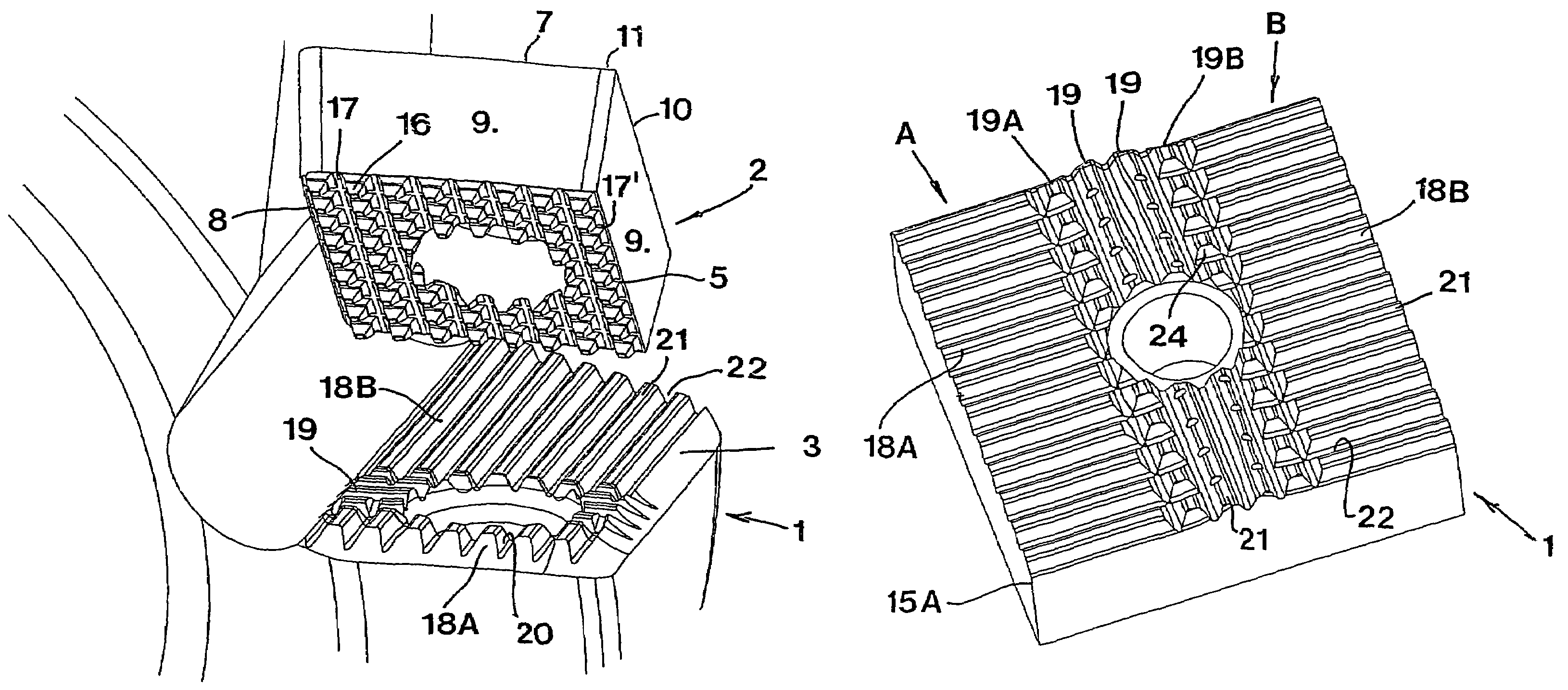
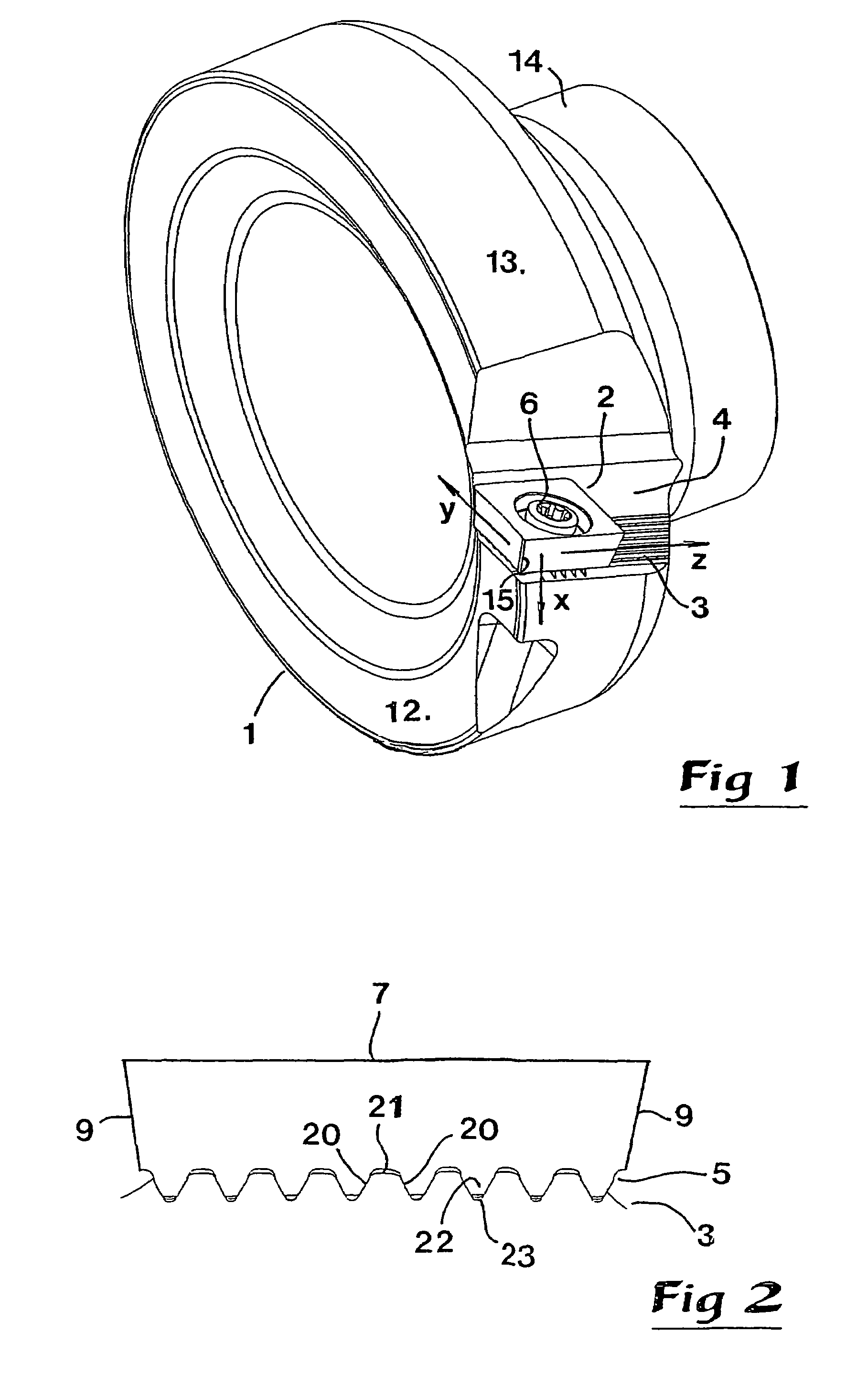
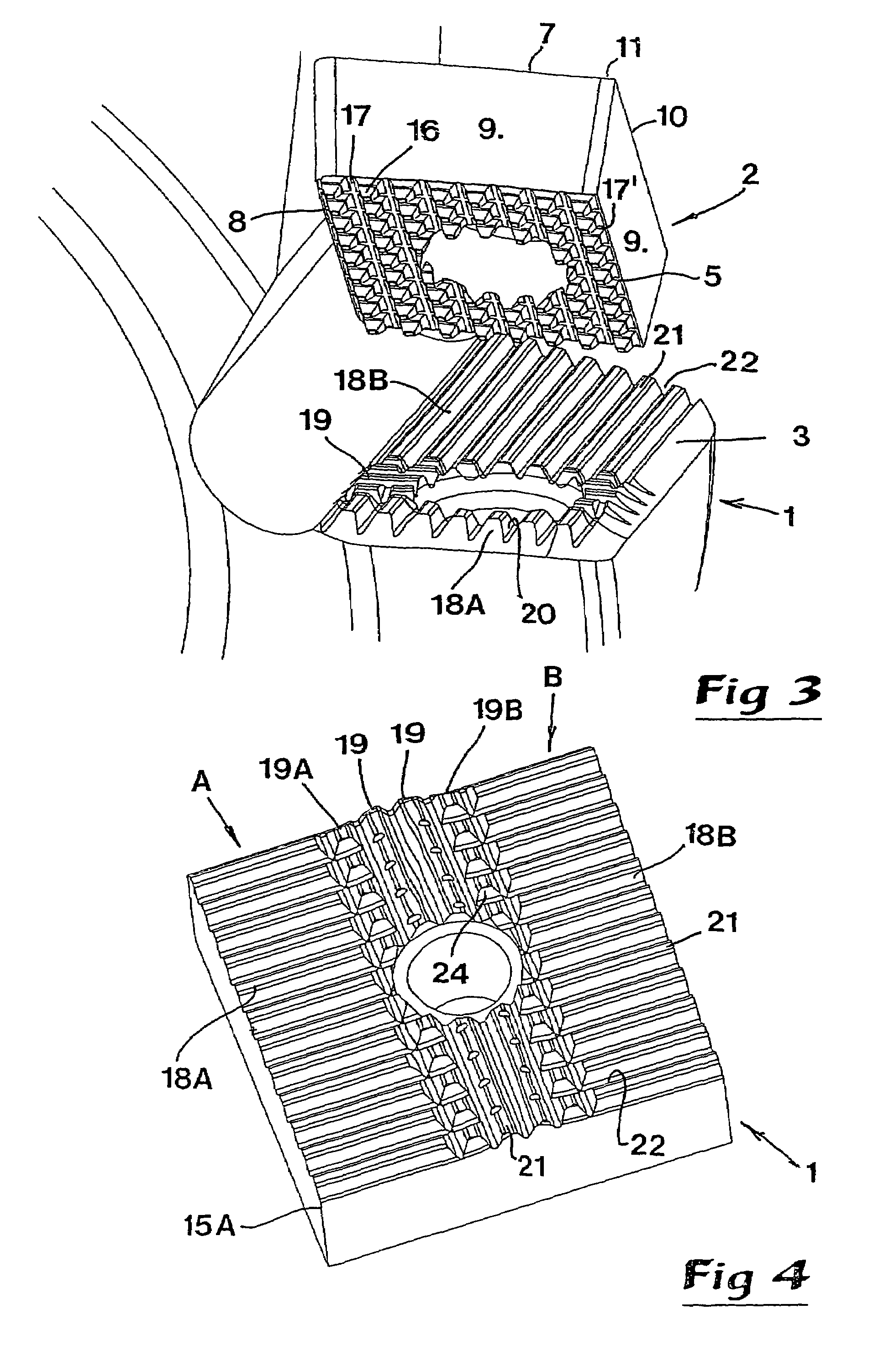
[0015]In FIG. 1, a rotatable cutting tool is shown exemplified as a milling cutter, which comprises a basic body 1, in the form of a cutter head, as well as a number of cutting inserts 2. For the sake of simplicity, only one such cutting insert is shown, although milling cutters in practice are provided with a plurality of peripherical and tangentially spaced cutting inserts. The individual cutting insert 2 is mounted in an insert seat designated 3, which is formed adjacent to a chip pocket 4 in the periphery of the basic body 1. The insert seat 3 consists of a first connecting surface of serration type, which is arranged to co-operate with a second serration connecting surface 5 (see FIGS. 2 and 3), which is formed on the bottom side of the cutting insert 2. The cutting insert 2 is fixed in the insert seat 3 by means of a suitable clamping member, which in the example consists of a screw 6, but which also may consist of a clamp or the like.

[0016]Before the two serration connecting ...


PUM

PropertyMeasurementUnit
anglesaaaaaaaaaa
surface fieldsaaaaaaaaaa
surface fieldaaaaaaaaaa

Abstract

The invention relates to a cutting tool of the type that comprises, on one hand, a basic body (1) having an insert seat, and on the other hand a cutting insert (2), which is detachably connected in the insert seat and rigidly secured in the same by means of connecting surfaces (3, 5) of serration type, one (3) of which forms said insert seat and comprises first and second ridges (18, 19), which extends perpendicularly to each other. According to the invention, at least the connecting surface that forms the insert seat (3) is formed with, on one hand, two spaced-apart surface fields or sets of a plurality of mutually parallel, first ridges (18A, 18B), which are arranged in extension of each other, and on the other hand one or more second, transverse ridges (19), which are located between the two sets of first ridges (18A, 18B). Furthermore, the invention also relates to a basic body of a cutting tool, as well as a cutting insert as such.

Description

TECHNICAL FIELD OF THE INVENTION[0001]In a first aspect, this invention relates to a cutting tool intended for chip-removing machining of the type that comprises, on one hand, a basic body having an insert seat, and on the other hand a cutting insert, which is detachably connected in the insert seat and rigidly secured in the same by means of connecting surfaces of serration type, one of which forms said insert seat and comprises first and second ridges, which extend perpendicularly to each other.[0002]In practice, the basic body may consist of, for instance, a drill shank or a cutter head, and the cutting insert of an indexable cutting insert.PRIOR ART[0003]A cutting tool of the above-mentioned type is previously known by WO 9900208 A1. In this case, the serration connecting surface serving as insert seat comprises two sets of ridges, which each are located in a separate surface field. This disposition of the ridges in only two sets or surface fields leads to the disadvantage that ...

Claims


Application Information

Patent Timeline
Patent Type & Authority Patents(United States)
IPC IPC(8): B23B27/16B23B51/00B23BB23C5/20B23C5/22
CPCB23C5/2221B23C2200/165B23C2210/168Y10T407/22Y10T407/23Y10T407/1906B23C2260/80B23C5/2213B23C5/20B23C5/16B23B27/16
Inventor PANTZAR, GORAN
Owner SANDVIK INTELLECTUAL PROPERTY AB
Why Eureka
Try Eureka