
Variable compression ratio dual crankshaft engine

a compression ratio and crankshaft technology, applied in the direction of positive displacement engines, hot gas positive displacement engine plants, combustion engines, etc., can solve the problems of mechanical damage to the engine, increase the amount of combustion heat transferred to the engine, and reduce the efficiency of the engin

Active Publication Date: 2009-09-08
FORD GLOBAL TECH LLC
View PDF19 Cites 24 Cited by
  • Summary
  • Abstract
  • Description
  • Claims
  • Application Information

AI Technical Summary

Benefits of technology

The invention is a dual crankshaft engine that allows for the variation of the compression ratio through the use of a common cylinder head and phasing device. The phasing device can temporarily interrupt synchronized rotation to change the angular position of one crankshaft relative to the other, resulting in a new, phase-shifted condition. This allows for the selective, dynamic, and temporary variation of the compression ratio, improving engine performance. The invention simplifies the mechanical linkages and couplings between the two crankshafts, making it easier to use traditional valve train and turbo / super-charging techniques.

Problems solved by technology

Maximum combustion efficiency occurs at maximum combustion pressures, but in the absence of compression-induced autoignition that can create undesirable noise and also do mechanical damage to the engine.
For engines already operating at peak efficiency / maximum pressure, however, the added inlet pressures created by turbochargers or superchargers would over compress the combustion mixtures, thereby resulting in autoignition, often called knock due to the accompanying sound produced.
This ignition timing retard results in a loss of engine operating efficiency and also an increase of combustion heat transferred to the engine.
Thus, a dilemma exists: the engine designer must choose one compression ratio for all modes.
A lower compression ratio, in turn, results in a loss of engine efficiency during light load operation, which is typically a majority of the operating cycle.
A particular shortcoming in all prior art attempts to dynamically vary the engine compression ratio by phase-shifting the synchronization of dual crankshafts is the mechanically cumbersome challenge of coupling two crankshafts oriented on polar opposite sides of an engine.
Practically speaking, phasing two crank shafts spaced so far apart is very difficult.
This leads to complicated and ineffectual mechanisms and designs which are not well suited to today's high efficiency engines and demanding customer expectations.
Furthermore, the prior art “headless” designs, in which opposing pistons work against each other from opposite ends of the same cylinder bore, do not readily accommodate the traditional poppet valve nor the time-tested techniques for seating and guiding valves in an internal combustion engine.
Thus, gas flow control methods must be employed in such prior art engines at the sacrifice of dependability and economy.
And yet again, phase-shifting of dual crankshafts results in a need to vary the timing of gas flow events to conform to “effective” top and bottom dead center timing.
The prior art designs significantly complicate any attempts to properly time gas flow events in these complex circumstances.
The prior art dual crankshaft engines that enable phase-shifting are notoriously unfriendly to the incorporation of traditional turbo- and super-charging systems that cooperate with the gas flow control system.

Method used


Image

  • Variable compression ratio dual crankshaft engine
  • Variable compression ratio dual crankshaft engine
  • Variable compression ratio dual crankshaft engine

Examples


Embodiment Construction

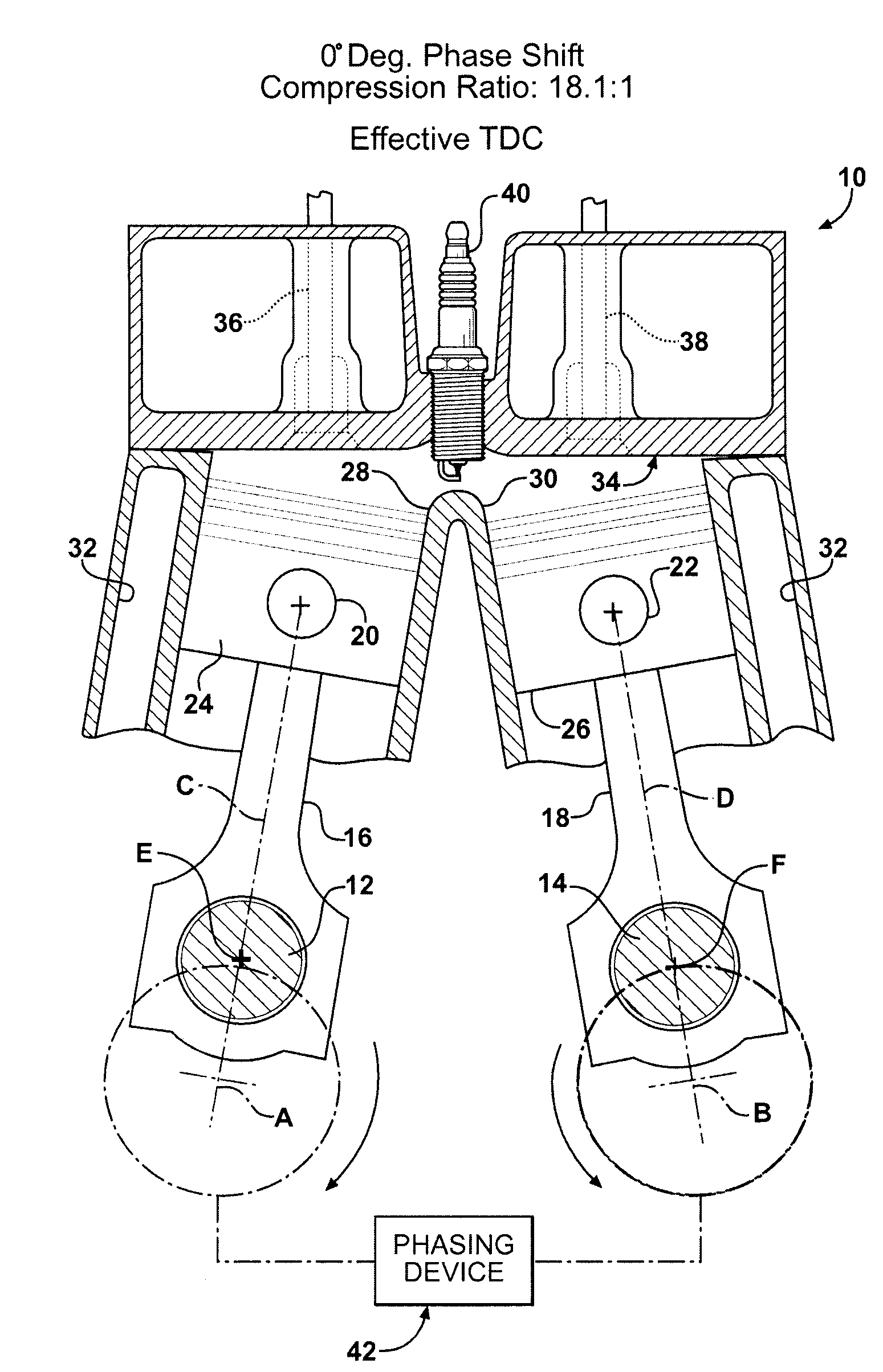
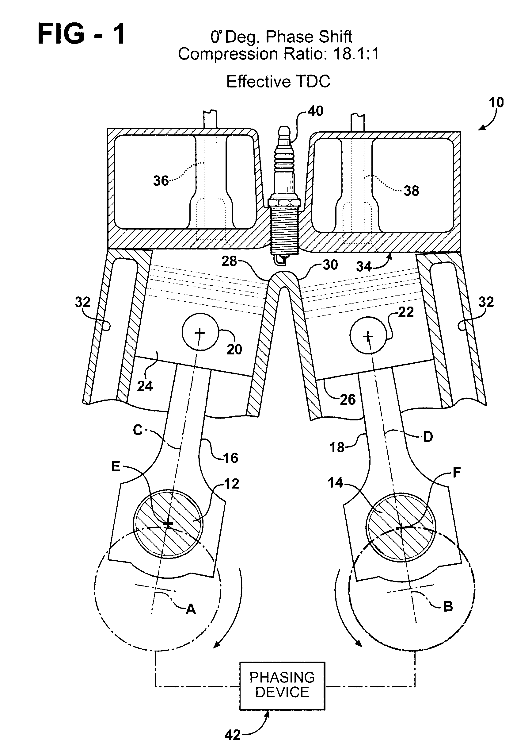
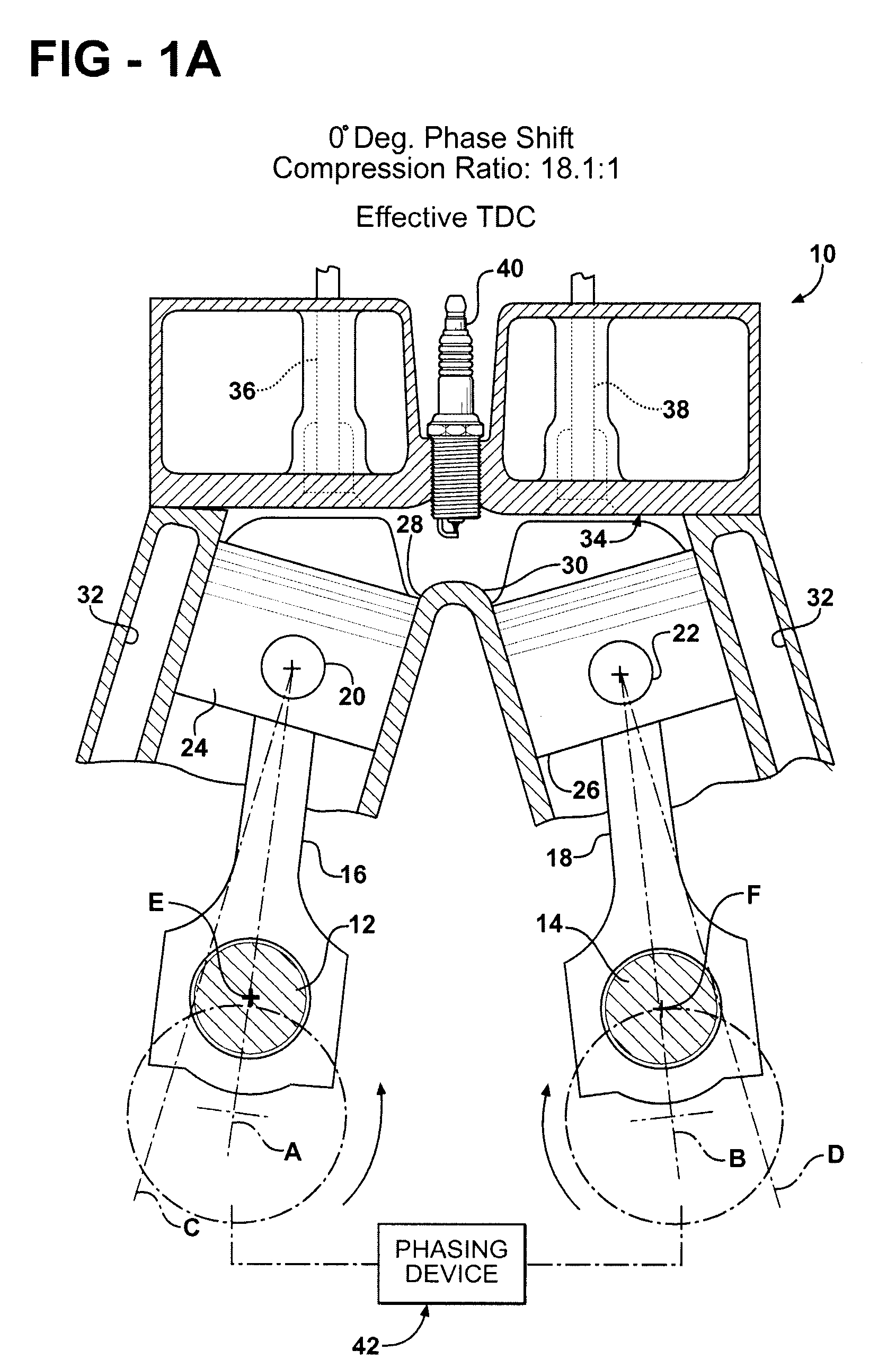
[0029]Referring to the Figures, wherein like numerals indicate like or corresponding parts throughout the several views, a schematic representation of an engine according to one exemplary embodiment of this invention is generally shown at 10 in FIG. 1. The engine 10 is of the dual crankshaft-type, wherein two crankshafts 12, 14 are supported for rotation about respective parallel axes A, B. The crankshafts 12, 14 may be of the typical type, supported in main bearings (not shown) in an engine crankcase assembly. A connecting rod 16, 18 is pivotally connected at a lower end thereof to each crankshaft 12, 14, respectively. This pivoting connection can be accomplished with standard techniques. An upper end of each connecting rod 16, 18 carries a pin 20, 22, respectively, for articulated connection to a piston 24, 26, respectively. The one piston 24 is disposed for reciprocating movement in a first cylinder 28, whereas the other piston 26 is similarly disposed for reciprocating movement ...


PUM


Abstract

A synchronized, dual crankshaft engine (10) uses a phase-shifting device (42) to alter the angular position of one crankshaft (12) relative to the other crankshaft (14) for dynamically varying the engine's developed compression ratio. Each crankshaft (12, 14) drives a respective connecting rod (16, 18) which, in turn, reciprocates a piston (24, 26) in a cylinder (28, 30). The center lines (C, D) of each cylinder (28, 30) are skewed relative to each other so that the pistons (24, 26) converge toward a common combustion chamber formed under a common cylinder head (34). Movable exhaust valves (36) are located above the piston (24) whose phase shifted orientation is retarded or lagging dead center conditions, whereas movable intake valves (38) are located above the piston (26) that is leading or advanced in its phase displacement relative to dead center conditions.

Description

CROSS REFERENCE TO RELATED APPLICATIONS[0001]None.BACKGROUND OF THE INVENTION[0002]1. Field of the Invention[0003]The subject invention relates generally to a variable compression ratio engine in which the compression ratio in the combustion chamber of an internal combustion engine is adjusted while the engine is running, and more specifically toward a synchronized, dual crankshaft engine that uses a phase-shifting device to alter the angular position of one crankshaft relative to the other for dynamically varying the engine compression ratio.[0004]2. Related Art[0005]Gasoline engines have a limit on the maximum pressure that can be developed during the compression stroke. When the fuel / air mixture is subjected to pressure and temperature above a certain limit for a given period of time, it autoignites rather than burns. Maximum combustion efficiency occurs at maximum combustion pressures, but in the absence of compression-induced autoignition that can create undesirable noise and a...

Claims


Application Information

Patent Timeline
Patent Type & Authority Patents(United States)
IPC IPC(8): F02B75/04
CPCF02B75/225F02B57/10
Inventor BERGER, ALVIN H.
Owner FORD GLOBAL TECH LLC
Learn More