Polarization scrambler, optical add/drop multiplexer, optical route switching apparatus and wavelength division multiplexing optical transmission system

a technology of optical transmission system and optical scrambler, which is applied in the direction of polarisation multiplex system, multiplex communication, and multiplex communication, etc., can solve the problems of variation in transmission quality degradation, transmission quality degradation due to pdm as discussed above cannot be ignored, and considerable degradation of transmission quality, etc., to reduce quality degradation and reduce quality degradation

Inactive Publication Date: 2009-09-01
FUJITSU LTD
View PDF11 Cites 8 Cited by
  • Summary
  • Abstract
  • Description
  • Claims
  • Application Information

AI Technical Summary

Benefits of technology

[0023]In the light of the above problems, an object of the present invention is to more mitigate degradation of the transmission quality due to PMD than the known techniques.
[0024]Another object of the present invention is to be able to set a scrambling speed to each path in a repeating apparatus such as an OADM apparatus or the like accommodating a plurality of paths set to respective wavelengths.
[0038]According to this invention, it is possible to perform polarization scrambling at a rotation speed at which the transmission quality is optimum according to a scheme and speed of modulation of the signal light and PMD of the path by means of the rotation speed controlling unit of the polarization scrambler to suppress degradation of the quality due to an inappropriate polarization scrambling speed. This enables high-quality transmission, where the effect of averaging the penalty due to PMD induced by polarization scrambling is sufficiently used.
[0039]It is also possible to perform polarization scrambling on at least one wavelength component contained in a signal light to be outputted from the multiplexing unit of an optical add / drop multiplexer and traveling on an arbitrary path, at a rotation speed at which the transmission quality is optimum, according to a scheme and speed of modulation of the wavelength component and PMD of the path. This allows mitigation of quality degradation caused by an inappropriate polarization scrambling speed, and allows high-quality transmission where the effect of averaging the penalty due to PMD induced by the polarization scrambling.

Problems solved by technology

Generation of the differential group delay between the modes causes a difference in transmission speed between the fast-wave and the slow-wave even in one optical pulse, which may induce considerable degradation of the transmission quality, depending on the state of the polarization particularly in high-speed signals at short pulse intervals.
In such high-speed optical transmission systems, degradation of the transmission quality due to PDM as discussed above cannot be ignored, which is one of factors that limit the transmission distance.
Degradation of the transmission quality due to PMD changes from zero to the maximum according to the input polarization state to a medium having PMD, which leads to variation in degradation of the transmission quality.
However, when an optical add / drop multiplexer (OADM: Optical Add / Drop Multiplexer), particularly, a reconfigurable optical add / drop multiplexer (R-OADM: Reconfigurable Optical Add / Drop Multiplexer) or a wavelength-convertible dynamic optical add / drop multiplexer (D-OADM: Dynamic Optical Add / Drop Multiplexer), or an optical HUB device is applied on a transmission path, the transmission path is more complicated than a point-to-point transmission path that the techniques disclosed in Patent Documents 1 to 3 suppose.
However, high speed scrambling causes that the received waveform is fluctuated at high speed, which may cause an increase in noise in the receiving system.
For this, it is sometimes difficult to keep excellent transmission quality only by setting the scrambling speed within a range of speed sufficient to average degradation of the transmission quality within one processing unit for error correction code.
However, the above known techniques do not disclose such constitution.
However, these documents do not mention a technique for setting the scrambling speed in a repeater such as an OADM device accommodating a plurality of paths set for respective wavelengths.

Method used


Image

  • Polarization scrambler, optical add/drop multiplexer, optical route switching apparatus and wavelength division multiplexing optical transmission system
  • Polarization scrambler, optical add/drop multiplexer, optical route switching apparatus and wavelength division multiplexing optical transmission system
  • Polarization scrambler, optical add/drop multiplexer, optical route switching apparatus and wavelength division multiplexing optical transmission system

Examples


first embodiment

[A1] Description of First Embodiment

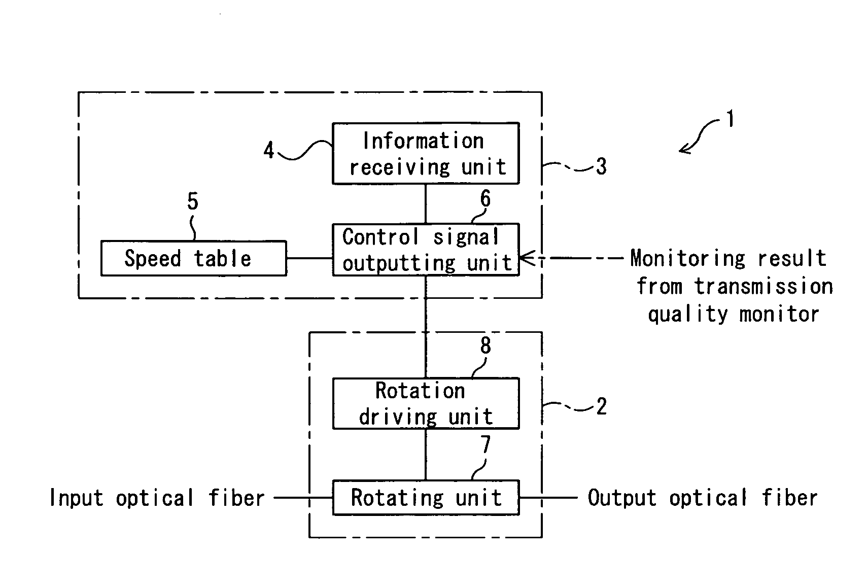
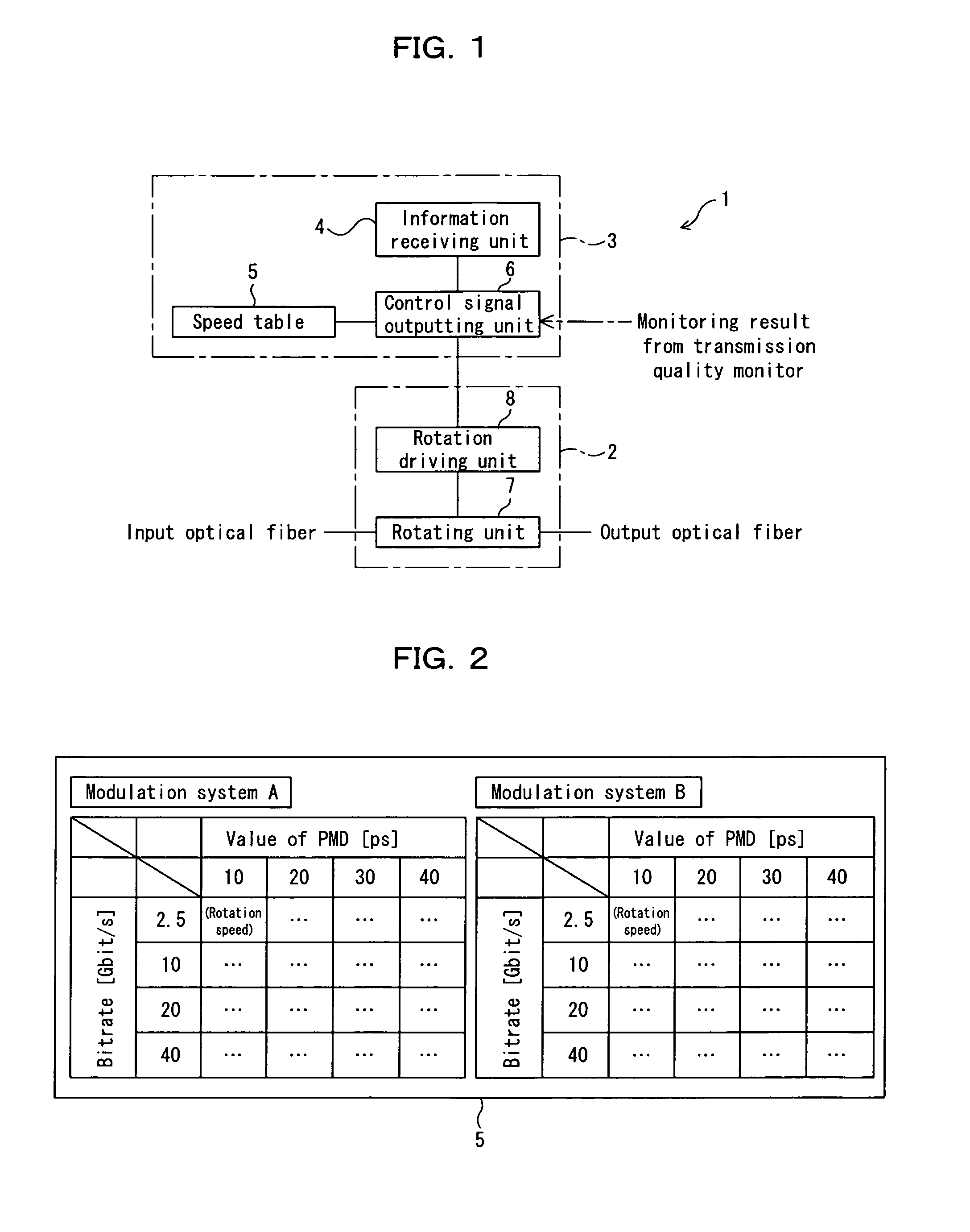
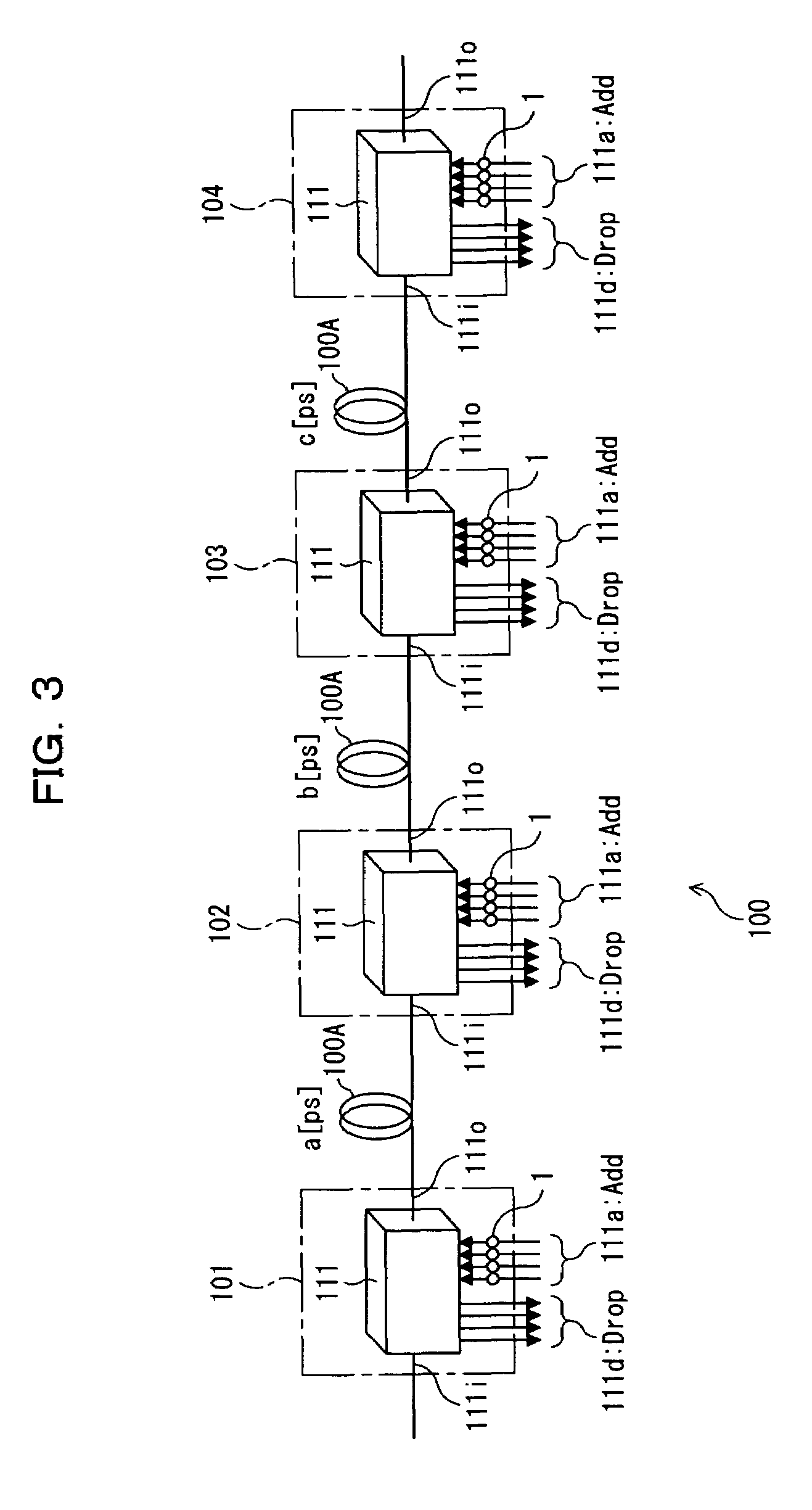
[0061]FIG. 1 is a block diagram showing a polarization scrambler according to a first embodiment of the present invention. The polarization scrambler shown in FIG. 1 is mounted in each of OADM nodes 101 through 104 in a wavelength division multiplexing optical transmission system 100, in which the OADM nodes 101 through 104 as being optical add / drop multiplexers are disposed on a transmission path 100A as shown in FIG. 3. The polarization scrambler 1 can variably set the speed of scrambling according to a change in modulating scheme and modulating speed of inputted signal light, and a fluctuation in DGD (or a value of PMD) of a path.

[0062]Each of the OADM nodes 101 through 104 shown in FIG. 3 has an add / drop function unit 111, along with the polarization scrambler 1.

[0063]The add / drop function unit 111 can output, through a drop port 111d, a wavelength component of a wavelength division multiplexed signal light inputted from the transmission path ...

second embodiment

[B1] Description of Second Embodiment

[0111]FIG. 14 is a diagram showing a wavelength division multiplexing transmission system 400 where OADM nodes 401 to 404 as being optical add / drop multiplexers according to a second embodiment of this invention are disposed on the transmission path 100A. The second embodiment differs from the first embodiment in that the polarization scrambler 1 similar to that described above with reference to FIG. 1 is disposed on not a path of the add port 111a but on a path of the through port 111t in each of the OADM nodes 401 to 404. Incidentally, the structure is basically the same as that according to the first embodiment excepting the position of the polarization scrambler 1.

[0112]Owing to the polarization scrambler 1 disposed on a path of each of the through ports 111t, it is possible to scramble the polarization state of a signal light on a path passing through the through port 111t in each of the OADM node 401 to 404 in the wavelength division multip...

third embodiment

[C] Description of Third Embodiment

[0135]FIG. 22 is a diagram showing an OADM node 701 as an optical add / drop multiplexer according to a third embodiment of this invention. In the third embodiment, each of polarization scrambling apparatuses 40 is disposed at a position (on a path) of the transmission input port 111i of the OADM node 701, unlike the first and second embodiments.

[0136]The OADM node 701 shown in FIG. 22 has a structure (refer to reference character 111A) as an add / drop function unit comprised of a DEMUX unit 115 and a MUX unit 116 similar to those described above with reference to FIG. 4, and the above-mentioned polarization scrambling apparatuses 40 each at a position of the transmission input port 111i.

[0137]The polarization scrambling apparatus 40 comprises a WSS 41, at least one (plural in FIG. 22) polarization scrambler 1 having the structure described above with reference to FIG. 1, and an optical coupler 42. The WSS 41 is a provisional demultiplexing unit whic...


PUM


Abstract

A polarization scrambler has a polarization state rotating unit rotating the polarization state of a signal light, and a rotation speed controlling unit controlling the rotation speed of the polarization state in the polarization state rotating unit on the basis of the speed and scheme of modulation of the signal light, and the value of polarization mode dispersion of a transmission path on which the signal light is to be transmitted. Degradation of the transmission quality due to PMD is more mitigated than the known techniques.

Description

BACKGROUND OF THE INVENTION[0001]1) Field of the Invention[0002]The present invention relates to a polarization scrambler, and an optical add / drop multiplexer, an optical route switching apparatus and a wavelength division multiplexing optical transmission system using the polarization scrambler.[0003]2) Description of Related Art[0004]It is general that the core of single mode fibers (SMF: Single Mode Fiber) used in optical transmission lines in optical transmission systems is not round but slightly elliptic, which induces birefringence. An optical signal inputted to such optical fiber is separated into two rectangular polarization mode components, that is, a fast-wave axis and a slow-wave axis.[0005]Since the transmission speed in the fiber differs between the two polarization mode components separated into the fast-wave and the slow-wave, differential group delay (DGD: Differential Group Delay) generates between the modes. Generation of the differential group delay between the mo...

Claims


Application Information

Patent Timeline
Patent Type & Authority Patents(United States)
IPC IPC(8): H04B10/00H04B10/12H04J14/06H04B10/07H04B10/2507H04B10/2569H04B10/27H04B10/29H04J14/00H04J14/02
CPCH04B10/2569H04B10/532H04J14/0204H04J14/0206H04J14/0241H04J14/0212H04J14/0209H04J14/0227H04J14/028H04J14/0283
Inventor NAKAMURA, KENTAROYUKI, MASAHIROHOSHIDA, TAKESHIISHIKAWA, GEORGE
Owner FUJITSU LTD
Why Eureka
Try Eureka