Airborne wind turbine electricity generating system

Inactive Publication Date: 2009-09-01
MELLER MOSHE
View PDF29 Cites 71 Cited by
  • Summary
  • Abstract
  • Description
  • Claims
  • Application Information

AI Technical Summary

Benefits of technology

[0010]It is another object of some embodiments of the invention to provide a new and improved system and method for generating electricity from wind using a lighter-than-air structure which is capable of varying its operational altitude and / or adapting to different wind velocities to thereby achieve a relatively high operational efficiency and provide a relatively high electricity-generating capacity while also having low construction and maintenance costs.
[0012]The angular stability control unit may also control the angular position of flaps relative to fins which are fixed relative the central shaft to aid in maintaining angular stability of the system.

Problems solved by technology

However, tall towers are expensive to build and once built, are subject to intense vibrations during operation.
Furthermore, land for building the towers to support such wind turbines is limited in view of numerous, known factors, including acquisition costs, environmental impact, zoning issues.
Although offshore winds, i.e., winds over bodies of water, are stronger than winds over land, the construction of support structures for wind turbines over a body of water is expensive, although there are significantly fewer limitations on the space for building support structures over such bodies of water.
The most notable limitation is that the construction of support structures for wind turbines is limited to certain depths of the bodies of water.
A drawback of this prior art system is that its power generation is very limited and it is not very efficient.
Among its drawbacks are that it is expensive to construct, includes complex mechanical parts and is not very practical.

Method used


Image

  • Airborne wind turbine electricity generating system
  • Airborne wind turbine electricity generating system
  • Airborne wind turbine electricity generating system

Examples


Embodiment Construction

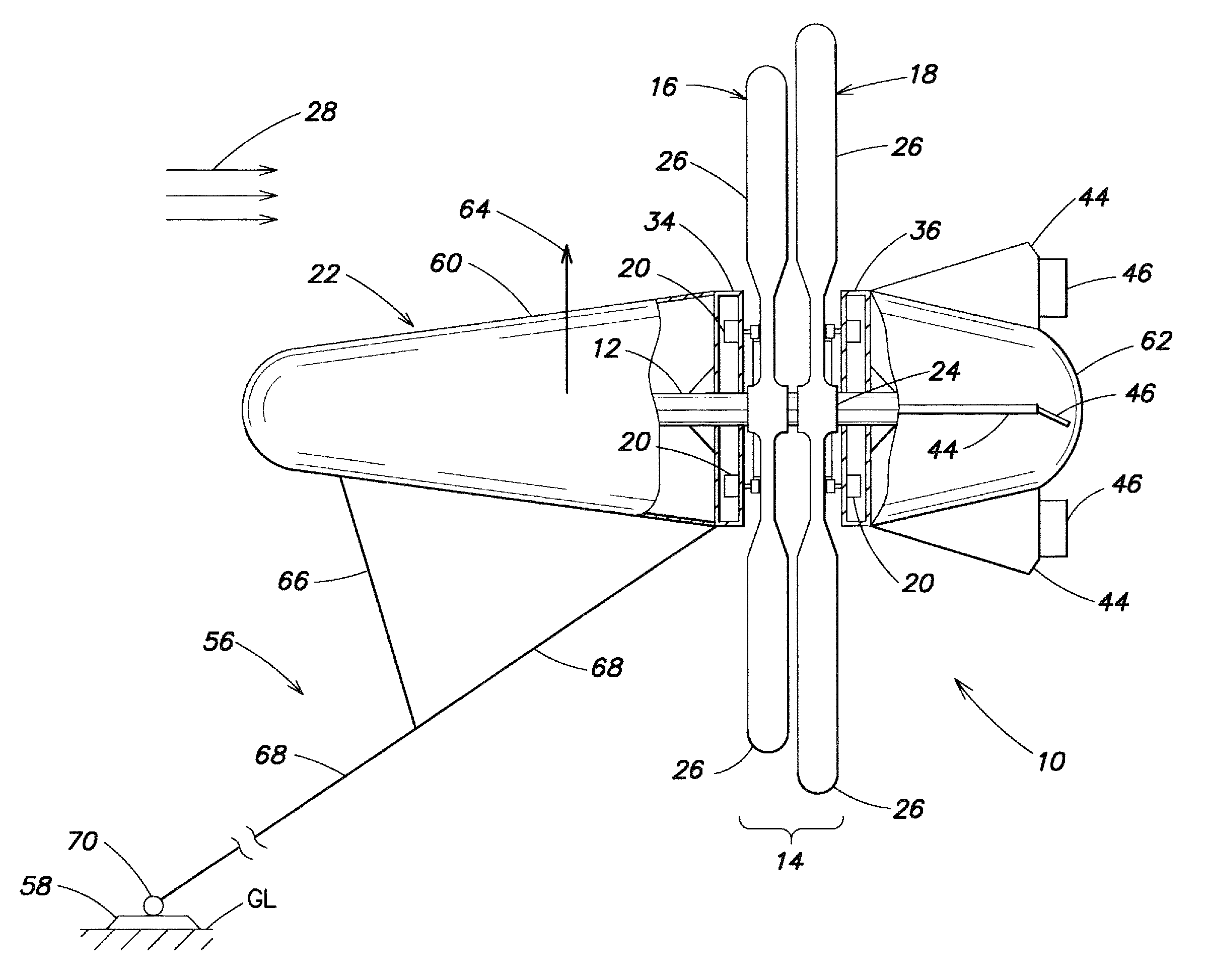
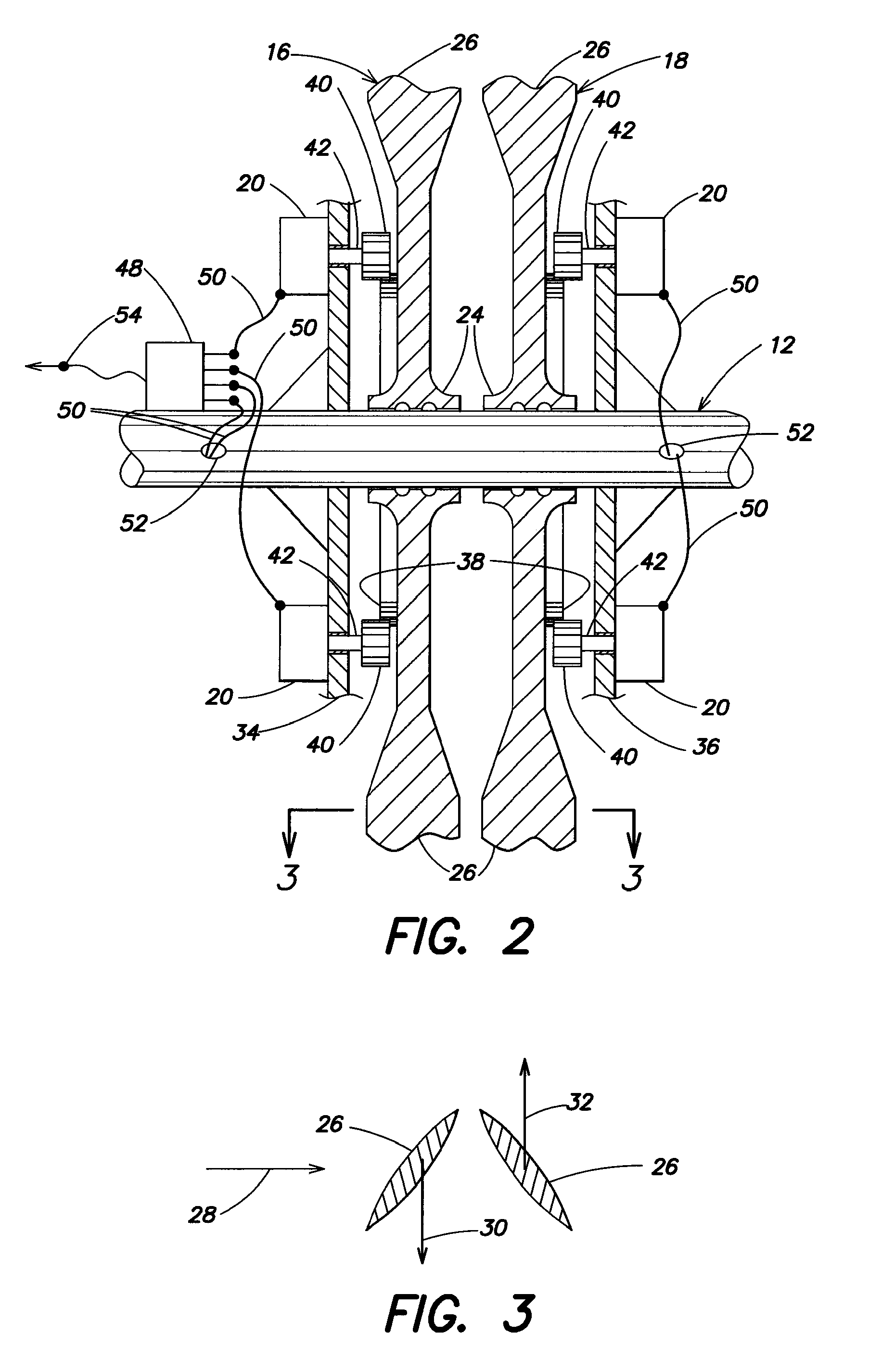
[0028]Referring to the accompanying drawings wherein the same reference numerals refer to the same or similar elements, an airborne wind turbine system in accordance with a first embodiment of the invention is designated generally as 10 and comprises a central shaft 12, a turbine section 14 including a front wind turbine 16 and a rear wind turbine 18 rotatably mounted to the shaft 12, generators 20 which convert rotation of the turbines 16, 18 into electricity, and a lifting structure 22 coupled to the turbine section 14 for generating a lifting force to enable the turbine section 14 to rise into the atmosphere. Although shaft 12 is referred to as a central shaft because it is preferably situated in the axial center of the system 12, it is conceivable that the shaft 12 may be positioned off-center, and thus the centrality of the shaft 12 should not be considered a limiting feature, but rather only a preferred feature.

[0029]Each of the front and rear turbines 16, 18 includes a respec...


PUM


Abstract

An airborne system for producing electricity from wind energy includes a shaft, at least two turbines rotatably mounted to the shaft and arranged to rotate independent of one another and in opposite directions when subjected to the same wind, and generators which convert rotation of the turbines into electricity. The magnitude of electricity generation by the generators is related to the magnitude of torque induced by the generators on the shaft, and the electricity generation by the generators may be controlled such that torques induced on the shaft by the generators is controlled such that a sum of torques induced on the shaft is substantially zero. A lifting structure generates a lifting force to lift the turbines to a desires altitude, and an anchoring system anchors the turbines relative to the ground. Generated electricity is conducted to users, to electricity storage, or to processing components.

Description

CROSS REFERENCE TO RELATED APPLICATION[0001]This application claims priority of U.S. provisional patent application Ser. No. 61 / 054,397 filed May 19, 2008, the entire contents of which are incorporated herein by reference.FIELD OF THE INVENTION[0002]The present invention relates generally to a wind turbine system for generating electricity and more specifically to a wind turbine system for generating electricity which is airborne, and includes both turbines and generators on a common, airborne structure.BACKGROUND OF THE INVENTION[0003]Wind energy is one of the most readily available forms of natural energy, which include solar, hydro, geothermal energy, and is therefore often used to generate electricity. The density of wind energy, in terms of watts per square meter, is one of the highest among other forms of natural energy.[0004]Existing systems for utilizing wind energy to generate electricity have certain disadvantages. For example, since wind velocity generally increases with ...

Claims


Application Information

Patent Timeline
IPC IPC(8): H02P9/00F03D1/04
CPCF03D1/025F05B2240/921Y02E10/72F05B2240/923F05B2240/922Y02E10/728F03D9/11F03D9/25F03D15/10F03D13/20F03D80/70Y02E70/30
Inventor MELLER, MOSHE
Owner MELLER MOSHE
Why Eureka
Try Eureka