
Method and apparatus for compensating temperature changes in an oscillator-based frequency synthesizer

a frequency synthesizer and oscillator technology, applied in the field of electromechanical circuits, can solve the problems of inability to use a cost-effective stand-alone crystal oscillator in a cellular system, the output of a crystal oscillator tends to drift, and the oscillator (xo) does not provide a means for controlling the frequency variation of the crystal

Inactive Publication Date: 2009-08-25
CAO WEIXUN
View PDF2 Cites 36 Cited by
  • Summary
  • Abstract
  • Description
  • Claims
  • Application Information

AI Technical Summary

Benefits of technology

[0011]This section is for the purpose of summarizing some aspects of the present invention and to briefly introduce some preferred embodiments. Simplifications or omissions in this section as...

Problems solved by technology

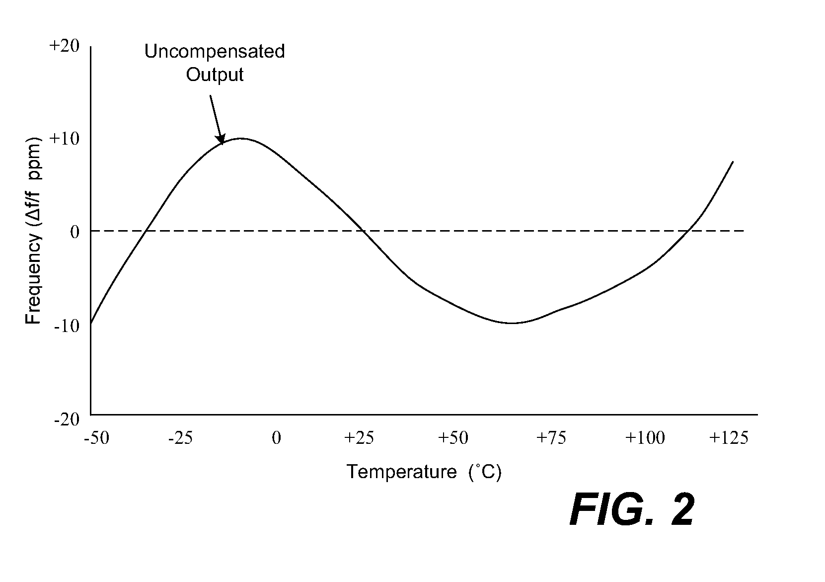
Unfortunately, the output of a crystal oscillator tends to drift with ages and temperature changes.
A simple crystal oscillator (XO) does not provide a means for controlling the crystal's frequency variation as the ambient temperature changes.
Due to the stringent requirements, it is not possible to use a cost-effective stand-alone crystal oscillator in a cellular system without some frequency tuning support from the base station.
Unfortunately, a DCXO circuit requires large capacitors to perform frequency corrections on the crystal oscillator.
Thus, it is extremely expensive to use a DCXO circuit, especially for a deep submicron CMOS process.
Furthermore, the switching of a large number of capacitors in the DCXO to adjust the crystal oscillator frequency may result in frequency beating effects that exhibit themselves as spurs in the generated frequency output.
However, such a voltage-controlled TCXO first requires a high quality crystal to meet the 3rd-order linear compensation requirement, which is expensive, particularly, when the size of the crystal is reduced.
It is also difficult to achieve high frequency stability and accuracy, as the maximal output frequency of a crystal oscillator is limited.
Further, it is difficult to control small frequency changes (e.g. less than 1.0 Hz) in a voltage-controlled TCXO as it is difficult to generate accurately an analog voltage in the range of micro volts.

Method used


Image

  • Method and apparatus for compensating temperature changes in an oscillator-based frequency synthesizer
  • Method and apparatus for compensating temperature changes in an oscillator-based frequency synthesizer
  • Method and apparatus for compensating temperature changes in an oscillator-based frequency synthesizer

Examples


Embodiment Construction

[0026]The detailed description of the present invention is presented largely in terms of functional blocks, procedures, logic blocks, processing, or other symbolic representations that directly or indirectly resemble the operations of a RF transmitter that can be used in wireless communications. These descriptions and representations are typically used by those skilled in the art to most effectively convey the substance of their work to others skilled in the art.

[0027]Reference herein to “one embodiment” or “an embodiment” means that a particular feature, structure, or characteristic described in connection with the embodiment can be included in at least one embodiment of the invention. The appearances of the phrase “in one embodiment” in various places in the specification are not necessarily all referring to the same embodiment, nor are separate or alternative embodiments mutually exclusive of other embodiments.

[0028]Referring now to the drawings, in which like numerals refer to l...


PUM


Abstract

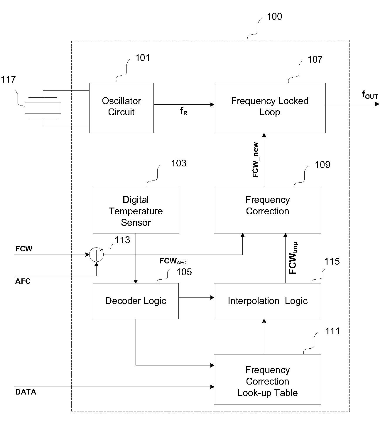
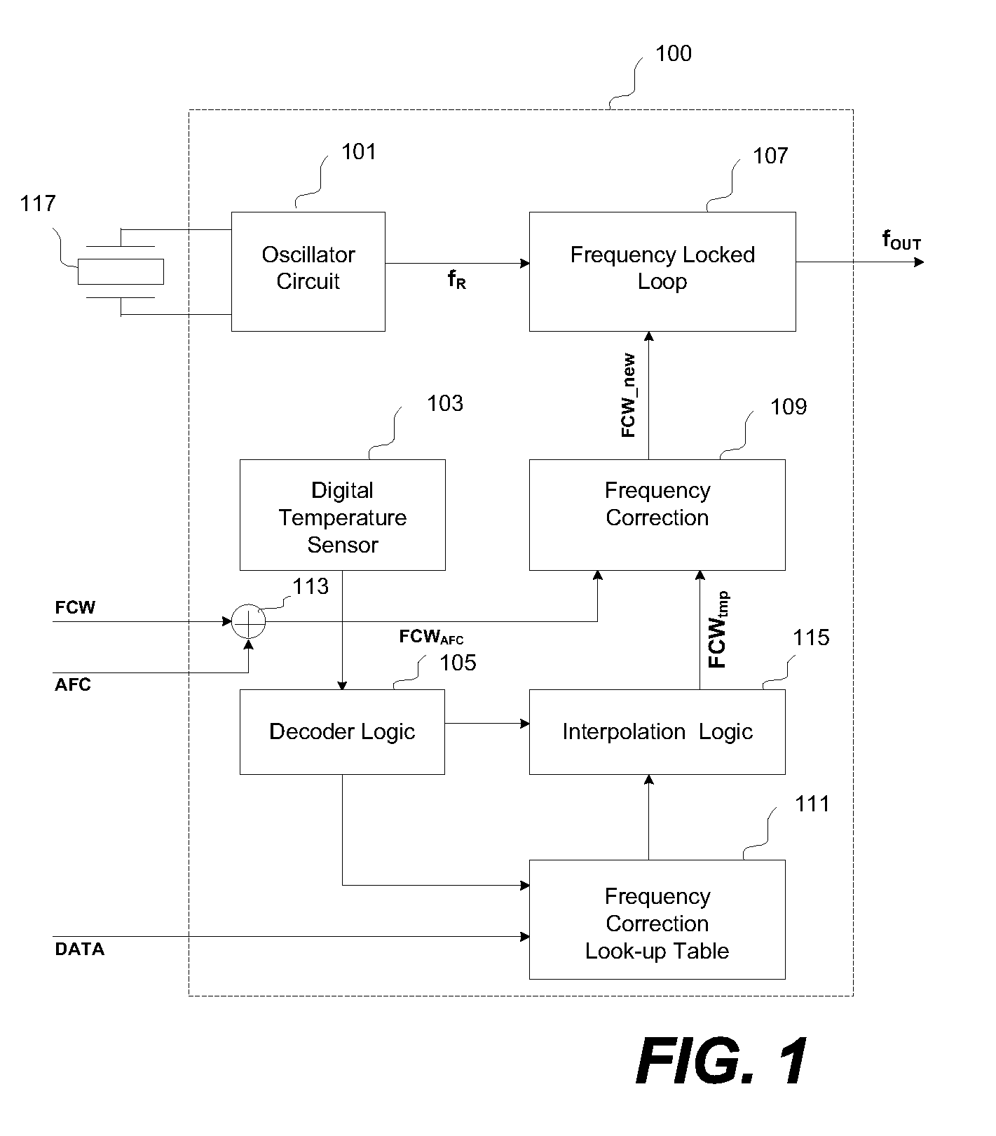
Architectures for compensating the frequency drift of an oscillator based frequency synthesizer circuit due to the change of temperature are disclosed. By applying a digitally controlled frequency word which represents the frequency difference between an output signal of a crystal oscillator and a temperature-compensated signal obtained from the output of a frequency synthesizer, the generated frequency signal is controlled so as to be temperature compensated over a wide temperature range. In one embodiment, a frequency locked loop is provided to perform functions to compensate for possible drifts in the reference signal. The frequency locked loop receives a digital frequency corrected control word based on at least a first parameter and a second parameter, wherein the first parameter is a combination of a fixed frequency control word and an automatic frequency correction word, and the second parameter is derived from an external source.

Description

CROSS REFERENCE TO RELATED APPLICATION[0001]This application claims the benefits of U.S. Provisional Application Ser. No. 60 / 998,813, entitled “Method and Apparatus for Temperature Compensation of an Oscillator Based Frequency Synthesizer”, filed on Oct. 13, 2007, the content of which is hereby incorporated by reference for all purpose in its entirety.BACKGROUND OF THE INVENTION[0002]1. Field of the Invention[0003]The present invention is generally related to electronic circuits, and more particularly, related to architectures for compensating the frequency drift of an oscillator based frequency synthesizer circuit due to the change of temperature are disclosed.[0004]2. Description of the Related Art[0005]To ensure all electronic parts to work properly or in synchronization, providing an accurate timing clock signal is very important in electronic circuit designs. Usually, such a timing clock signal is produced in a crystal oscillator that is an electronic circuit using the mechanic...

Claims


Application Information

Patent Timeline
IPC IPC(8): H03C3/06H03L1/00
CPCH03L1/026H03L7/18H03L1/027H03L7/0991
Inventor CAO, WEIXUN
Owner CAO WEIXUN
Learn More