
SAW filter operable in a piston mode

a piston mode and filter technology, applied in the field of surface acoustic wave filter, can solve the problems of reducing the transducer aperture, and causing both spurious rejection and ripple in the pass band

Active Publication Date: 2009-08-18
QORVO US INC
View PDF8 Cites 145 Cited by
  • Summary
  • Abstract
  • Description
  • Claims
  • Application Information

AI Technical Summary

Benefits of technology

[0008]Embodiments of the invention may include SAW transducers, wherein more acoustic energy is generated by the transducer in one direction or is more sensitive to the acoustic energy coming from the one direction. Further, a SAW transducer may have acoustic reflectors, and wherein directionality is a result o

Problems solved by technology

An undesirable feature and often difficult problem to solve when designing a narrow band SAW filter, especially on quartz, is presented by a presence of transverse modes.
The result can produce both ripple in the pass band and spurious rejection.
One approach reduces the transducer aperture, which reduces the number of guided modes and thereby increases their frequency difference.
The drawback of this approach is that a small aperture has to be chosen, resulting in high impedances.
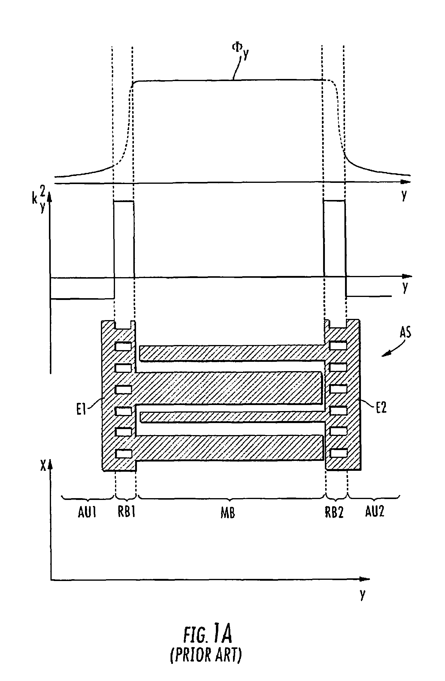
While this method results in some improvement, it is limited by the main transverse mode extending outside of the acoustic aperture, making it difficult to construct an apodization desirably reproducing the mode shape.
Some improvements in the filter response result, but parasitics still remain.

Method used


Image

  • SAW filter operable in a piston mode
  • SAW filter operable in a piston mode
  • SAW filter operable in a piston mode

Examples


Embodiment Construction

[0025]The present invention will now be described more fully hereinafter with reference to the accompanying drawings, in which embodiments of the invention are shown. This invention may, however, be embodied in many different forms and should not be construed as limited to the embodiments set forth herein. Rather, these embodiments are provided so that this disclosure will be thorough and complete, and will fully convey the scope of the invention to those skilled in the art.

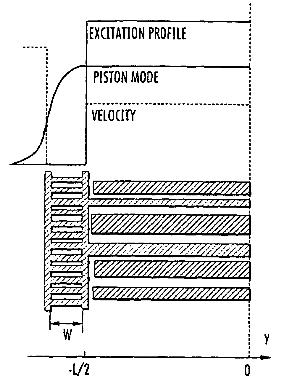
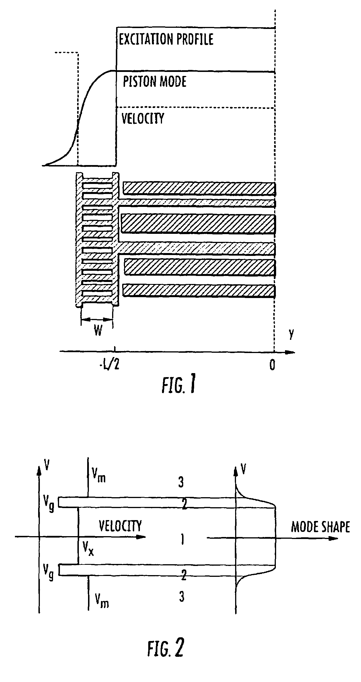
[0026]Referring now to FIG. 2, consider a transducer being described by three transverse regions including a center region, an edge region and a bus bar region. With such a transducer, it is generally straightforward to compute velocities and shapes of various guided modes using a scalar potential approach. As illustrated with continued reference to FIG. 2, a piston mode is characterized by a flat amplitude in the center region, an exponentially decreasing amplitude in the bus bars and a sine or cosine shape in t...


PUM


Abstract

A SAW transducer includes a pair of opposing bus bars formed on a surface of a piezoelectric substrate with a plurality of interdigital electrodes extending from each of the opposing bus bars. A center region and opposing edge regions are formed, wherein each edge region is proximate each bus bar and includes free end portions of the electrodes such that a wave velocity in each edge region is substantially lower than a wave velocity in the bus bars and in the center region, and wherein electro-acoustic sources extend into the edge regions for providing a SAW transducer having the piezoelectrically excited strongest mode is a piston mode with an amplitude distribution generally flat across most of the resonator area.

Description

FIELD OF THE INVENTION[0001]The present invention generally relates to surface acoustic wave (SAW) filters and more particularly to SAW transducers where the piezoelectrically excited strongest mode is a piston mode having an amplitude distribution generally flat across most of a central portion of the transducer aperture.BACKGROUND OF THE INVENTION[0002]An undesirable feature and often difficult problem to solve when designing a narrow band SAW filter, especially on quartz, is presented by a presence of transverse modes. With a finite aperture for a SAW device, several guided modes can propagate instead of one. The effect of these transverse modes is to add several other undesirable responses to an otherwise ideal filter response, shifted in frequency and to a lower level. The result can produce both ripple in the pass band and spurious rejection. Several approaches have been used to solve this problem.[0003]One approach reduces the transducer aperture, which reduces the number of ...

Claims


Application Information

Patent Timeline
IPC IPC(8): H01L41/09
CPCH03H9/02858H03H9/6496H03H9/1457H03H9/02881
Inventor SOLAL, MARC
Owner QORVO US INC
Learn More