
Vehicular lighting fixture with non-directional dispersion of light

a technology of non-directional dispersion and vehicle lighting, which is applied in the direction of mobile visual advertising, lighting support devices, instruments, etc., can solve the problems of difficult to perceive most bumper stickers or other signage at night or in other low level light conditions, limited self-expression of individuals through vehicle signage and bumper stickers, and limited space for self-expression on the rearward surface of the vehicl

Inactive Publication Date: 2009-08-18
REBO LIGHTING & ELECTRONICS LLC
View PDF18 Cites 204 Cited by
  • Summary
  • Abstract
  • Description
  • Claims
  • Application Information

AI Technical Summary

Benefits of technology

"The patent describes a motor vehicle lighting system that has a screen on the back of the vehicle that can display interesting visual effects using both visible and ultraviolet light. The system includes a primary light source for traditional vehicle lighting and a secondary light source that can be activated to produce the visual effects. The system is controlled so that the secondary light source is automatically de-energized when the primary light source is activated. This helps to avoid any conflict between the two lighting functions and ensures that the vehicle's rearward surface is always available for traditional lighting while still being able to display interesting visual effects."

Problems solved by technology

Most bumper stickers or other signage, however, are difficult to perceive at night or in other low level light conditions.
Thus, the self-expression of an individual through the medium of vehicle signage and bumper stickers is generally limited to daylight conditions.
Furthermore, the available space for self-expression indicia is somewhat limited on the rearward surface of the vehicle.
For example, it is not possible to cover the spaces reserved for CHMSL and other lighting features because of the safety issues.

Method used


Image

  • Vehicular lighting fixture with non-directional dispersion of light
  • Vehicular lighting fixture with non-directional dispersion of light
  • Vehicular lighting fixture with non-directional dispersion of light

Examples


Embodiment Construction

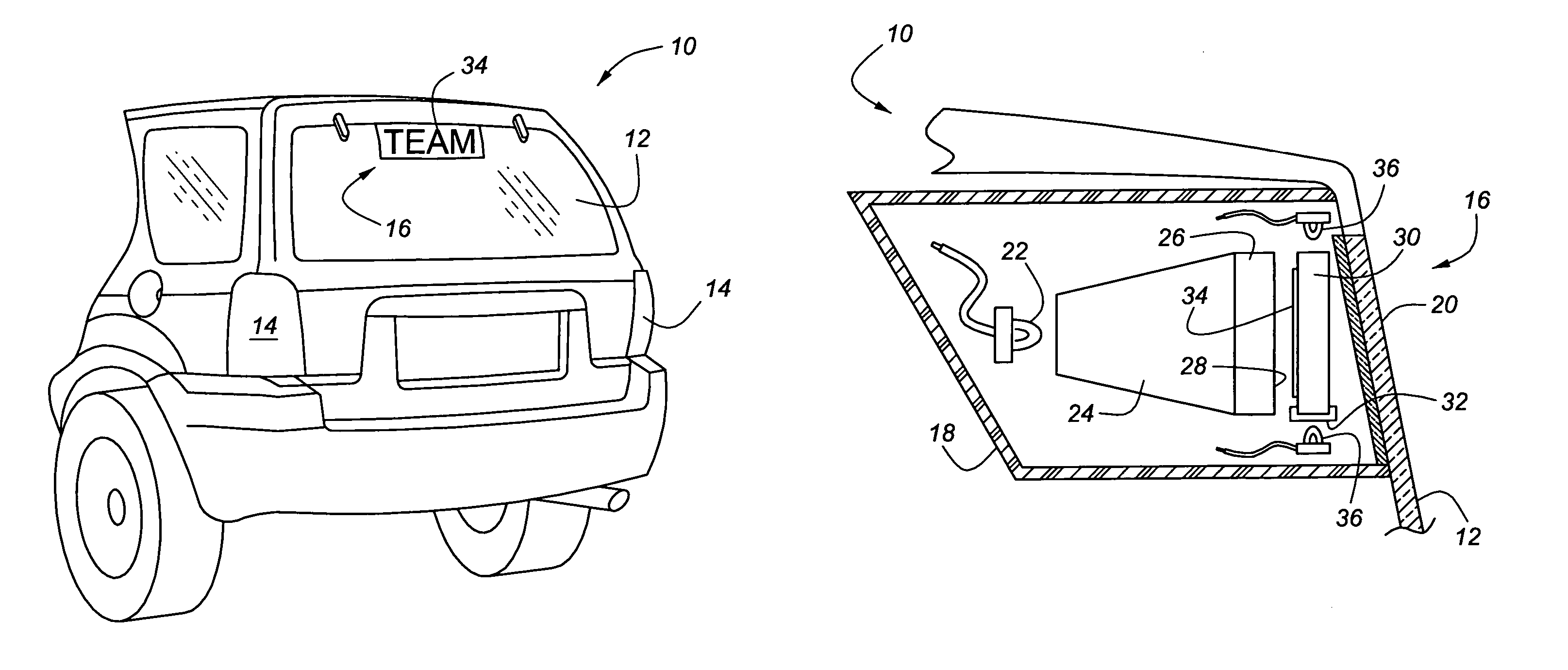
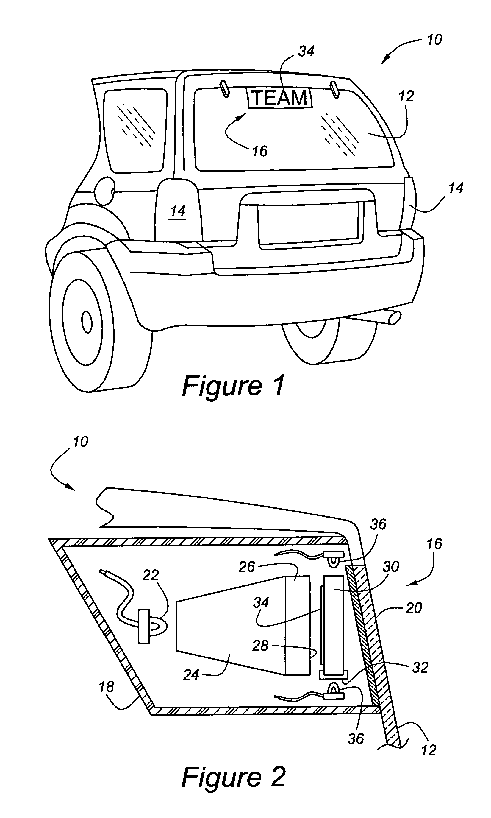
[0019]Referring to the figures, wherein like numerals indicate like or corresponding parts throughout the several views, a representative automobile is generally shown at 10 in FIG. 1. The automobile 10 includes a rearwardly facing exterior surface which includes a rear window 12, a pair of rear brake light assemblies 14, and other standard features. A CHMSL assembly, generally indicated at 16, is supported for viewing through the rear window 12. When a driver touches the brake pedal and thus activates the braking system, the CHMSL assembly 16 is energized, together with the brake lights 14, to illuminate an elongated, generally rectangular red region signaling rearward drivers of a brake-induced deceleration.

[0020]Referring to FIG. 2, the CHMSL 16 includes a housing 18 which is mounted or fixed to the vehicle 10. In some vehicles, the housing 18 will be suspended from the inner roof or headliner portion, whereas in other vehicles the housing 18 will be mounted on a rear deck lid or...


PUM


Abstract

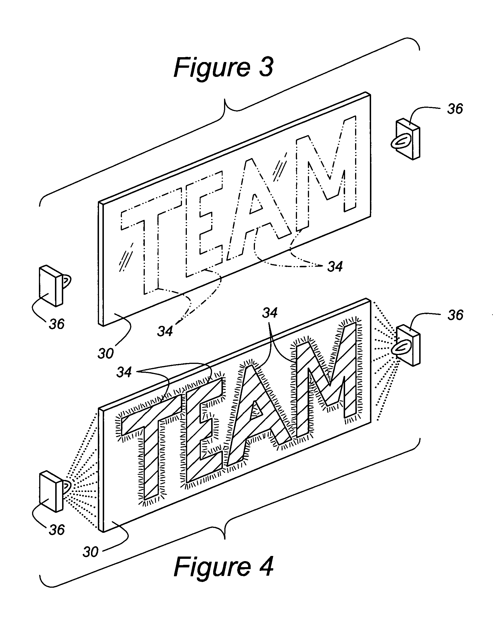
A CHMSL (16) or other lighting system feature of an automobile (10) includes a feature for presenting personal expressions in the form of words or symbols but is automatically deactivated when the regular vehicle lighting system is in use. The personal expression is fixed in a tangible medium by way of phosphor-coated indicia (34) placed within a UV impervious housing (18). A secondary UV light source (36) selectively energizes the phosphor-coated indicia (34) so that the irradiated material glows and is visible through a light transmissive screen (20). The light transmissive screen (20) is provided with a UV blocking agent so that harmful UV rays do not escape the housing (18). The phosphor-coated indicia (34) can be mounted on a removable transparent plate (30), on light dispersion optics (24, 26), or on the inner face of the light transmissive screen (20). A control circuit (42″) manages the primary light source (22) and the secondary UV light source (36) so that only one of the light sources can be energized at any one time.

Description

[0001]This invention claims priority to U.S. Provisional Patent Application No. 60 / 588,481, filed Jul. 16, 2004.BACKGROUND OF THE INVENTION[0002]1. Field of the Invention[0003]An ultraviolet light induced indicia for a motor vehicle, and more particularly, a stop or other external lighting system capable of displaying a UV light induced indicia when not in regular use as a stop or other light feature.[0004]2. Related Art[0005]Center high mounted stop lamp (CHMSL) assemblies for motor vehicles are one example of a regular light assembly having a primary purpose in this case of indicating a braking condition. CHMSL's are typically mounted in the rear window, or on the rear deck, of an automobile and are wired to light an elongated generally rectangular region with the brake-light system. They provide increased visibility to the brake-light system, and thus comprise an important part of the vehicle safety system.[0006]Bumper stickers and other rear vehicle signage have become an accept...

Claims


Application Information

Patent Timeline
Patent Type & Authority Patents(United States)
IPC IPC(8): B60Q1/26
CPCB60Q1/302G09F21/04B60Q1/50B60Q1/503
Inventor BUCHER, LLOYD KEITHANDERSON, JR., JAMES BURR
Owner REBO LIGHTING & ELECTRONICS LLC
Learn More