
Lamp fixture

a lamp fixture and lamp body technology, applied in the field of improved lamp fixtures, can solve the problems of large differences in light levels in the visual field, discomfort of human beings, and troublesome people, and achieve the effect of improving the uniformity of the lamp and preventing glar

Active Publication Date: 2009-08-18
IND TECH RES INST
View PDF13 Cites 9 Cited by
  • Summary
  • Abstract
  • Description
  • Claims
  • Application Information

AI Technical Summary

Benefits of technology

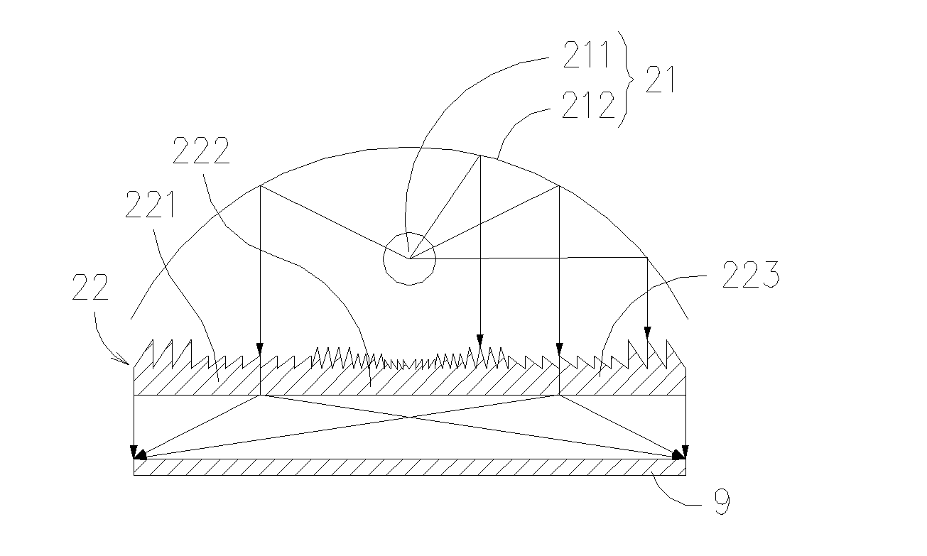
The present invention provides an improved lamp fixture with anti-glare function. It includes a lamp, a light source, and a light-control unit. The light-control unit comprises a semi-Fresnel microstructure and a light-control microstructure. The semi-Fresnel microstructure is used for diffusing / collimating light from the light source, while the light-control microstructure is used for controlling the resulting lighting angle for improving illuminance uniformity. The light-control microstructure can be a symmetrical or unsymmetrical shape. The improved lamp fixture with anti-glare function can also include a screen that reflects light emitting from the light source and a reflective layer on the reflective surface. The light source can be an incandescent bulb, a fluorescent lamp, a light emitted diode, or a combination thereof. The semi-Fresnel microstructure can be composed of reflective or refractive microelements. The light-control microstructure can be a microstructure array of symmetrical or unsymmetrical shape. The invention provides an improved lamp fixture with anti-glare function that prevents glare and improves illuminance uniformity.

Problems solved by technology

For example, it may happen when there are two light sources illuminating a same general area, such as a study room, in that an area light such as the luminaire fitted on the ceiling is used for lighting the whole study room while a task light such as a desktop lamp is used for lighting a working area on the desk, thereby, large differences in light levels will be caused in the visual field.
Moreover, indirect glare occurs when light from windows or overhead lighting is reflected off shiny surfaces in the field of view, such as terminal screens, desks and other office equipment, which is considered to be the most commonly experienced glare and is the one that causes most discomfort to human eye.
Therefore, as the indirect glare viewed in the field of view is substantially a kind of secondary light originating from and reflected by a glassy surface of a reading material being viewed by a person, the glare troubling the person, being the reflection of the light shining on the reading material, is impossible to be avoided without changing his or her normal orientation to the reading material.
Indirect glare can be a significant problem, since it may be the cause of burred images, strenuous reading, low reading efficiency, and even severe eyestrain and headaches.
However, since the use of such reflective filter will result a portion of light to be dissipate during the reflection, the light efficiency and the brightness of any luminaire using such anti-glare structures are reduced and thus may not be satisfactory.
However, it is disadvantageous in that: the use of such reflective screen will result in the luminaire to have smaller lighting area, not to mention that it is much more complicated to design and manufacture.
In addition, any luminaire designed with such soft screen will have poor light efficiency inferior to those without.
However, it is disadvantageous in that: the use of such reflective screen will result in the luminaire to have smaller lighting area, not to mention that the overall light efficiency of the luminaire is adversely affected.
From the above description, it is noted that although those conventional anti-glare structures can function effectively in glare improvement, they are all suffered by problems of smaller lighting area and lower light efficiency.

Method used


Image

  • Lamp fixture
  • Lamp fixture
  • Lamp fixture

Examples


Embodiment Construction

[0048]For your esteemed members of reviewing committee to further understand and recognize the fulfilled functions and structural characteristics of the invention, several preferable embodiments cooperating with detailed description are presented as the follows.

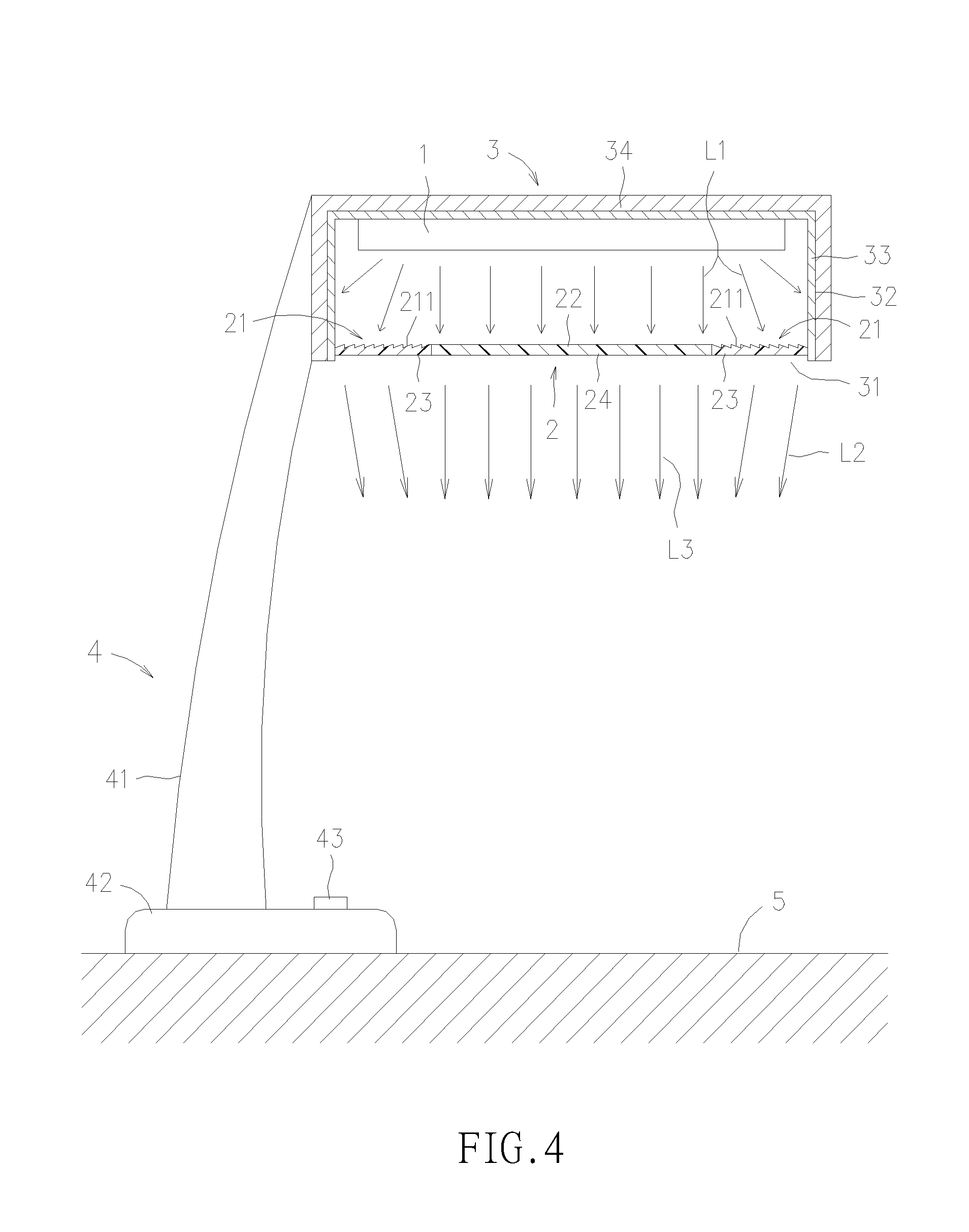
[0049]Please refer to FIG. 4, which is a cross-sectional view of an improved lamp fixture with anti-glare function according to an exemplary embodiment of the invention. The lamp fixture of FIG. 4 includes a light source 1, a light-control unit 2, a screen 3 and a lamp 4. The lamp 4 is composed of a post 41, a base 42 and at least a switch, represented by the one switch 43 shown in FIG. 4, in which the post 41 and the switch 43 are mounted on the base 42 while the base is placed on a surface 5, such as a desk top. As seen in FIG. 4, the light source 1, the light-control unit 2 and the screen 3 are all being mounted to the top of the post 41. As the switch 43 is mounted on the base 42, it can be connected to a power source, or...


PUM


Abstract

An improved lamp fixture with anti-glare function is disclosed, which comprises: a lamp; a light source; and a light-control unit, composed of a semi-Fresnel microstructure and a light-control microstructure; wherein the light source and the light-control unit are mounted on the lamp; and the semi-Fresnel microstructure is used for diffusing / collimating light of the light source while the light-control microstructure is used for controlling the resulting lighting angle. With the aforesaid lamp fixture, not only glare can be prevented, but also uniformity of the lamp fixture is improved.

Description

FIELD OF THE INVENTION[0001]The present invention relates to an improved lamp fixture with anti-glare function, and more particularly, to an anti-glare desktop lamp capable of controlling its lighting direction and distribution by the formation of a semi-Fresnel microstructure and a light-control microstructure without adversely affecting its light efficiency, and thereby, not only glare can be prevented, but also uniformity of the lamp is improved.BACKGROUND OF THE INVENTION[0002]There are three types of glare: direct, contrast and indirect. Direct glare occurs when there are bright light sources directly in the operator's field of view. Windows are often a source of direct glare, or one may experience the direct glare by looking straightly to the sun or a light bulb. Contrast glare is where one part of the vision area is much brighter than another. Usually it is caused by large differences in light levels within the visual field. For example, it may happen when there are two light...

Claims


Application Information

Patent Timeline
Patent Type & Authority Patents(United States)
IPC IPC(8): F21V5/02
CPCF21S6/003F21S13/12F21V5/045F21Y2103/00
Inventor LIN, JIAN-SHIANLAI, CHIEH-LUNGTSAI, JEN-HUIWU, TUNG-CHUAN
Owner IND TECH RES INST
Learn More