All-digital cantilever controller
a controller and cantilever technology, applied in the field of scanning probe microscopes, can solve the problems of inability to meet all of these requirements, the uncertainty level involved in the final implementation, and the thermal drift of analog components, so as to maximize the execution speed of algorithms, improve the accuracy of algorithms, and reduce the cost of implementation
- Summary
- Abstract
- Description
- Claims
- Application Information
AI Technical Summary
Benefits of technology
Problems solved by technology
Method used
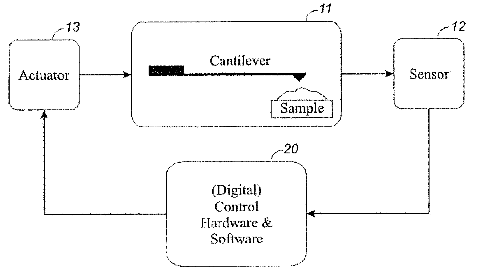
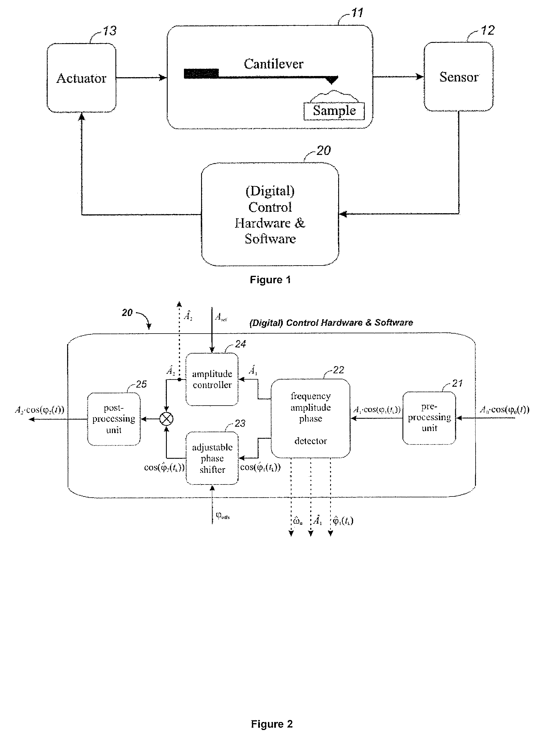
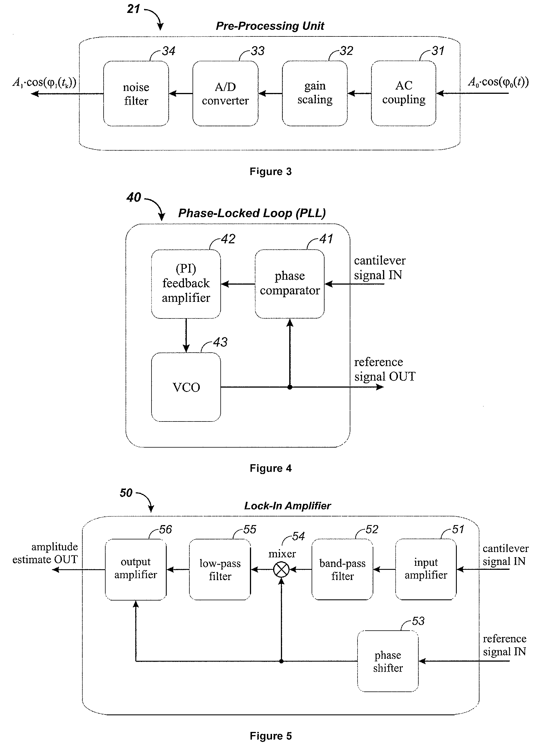
Image

Examples
example
[0092]The expression q3[4,23]=q1[0,11]*q2[7,16] implies one first has to multiply:
q1[0,11]*q2[7,16]=tmp[8,27],
then shorten and shift the intermediate result tmp[8,27] such that it becomes q3[4,23], in this case multiply the intermediate result by 223−(11+16)=2−4= 1 / 16, or simply shift the intermediate result right by 4:
tmp[8,27]>>4=tmp[12,23],
and finally shortening this 36 bit number to a 28 bit number by discarding the 8 most significant bits:
q[4,23]=tmp[0:4,23].
A Method for Producing an Optimal Fixed-Point Controller Algorithm
[0093]Algorithm precision, or desired word-length, and algorithm execution speed are conflicting requirements: the higher the desired precision, the longer it takes to execute the calculations. In addition, a typical digital processor only has limited logic resources, also called a processor's real estate. Even if one wishes to do all calculations using 64 bit integers, this is often not possible because of the limited resources.
[0094]To find an optimal trade...
PUM
 Abstract
Description
Claims
Application Information
 - R&D
- Intellectual Property
- Life Sciences
- Materials
- Tech Scout
- Unparalleled Data Quality
- Higher Quality Content
- 60% Fewer Hallucinations
Browse by: Latest US Patents, China's latest patents, Technical Efficacy Thesaurus, Application Domain, Technology Topic, Popular Technical Reports.
© 2025 PatSnap. All rights reserved.Legal|Privacy policy|Modern Slavery Act Transparency Statement|Sitemap|About US| Contact US: help@patsnap.com