
Carrier-suppressed optical time domain multiplexing

a carrier-suppressed, optical time domain technology, applied in multiplex communication, time-division optical multiplex system, line-transmission details, etc., can solve the problem of difficult to produce optical path difference between two tributaries, the phase relationship between successive pulses is unknown and constantly changing, and the non-carrier-suppressed optical signals do not compensate for neighboring pulse interaction

Active Publication Date: 2009-08-11
MOLEX INC
View PDF4 Cites 19 Cited by
  • Summary
  • Abstract
  • Description
  • Claims
  • Application Information

AI Technical Summary

Benefits of technology

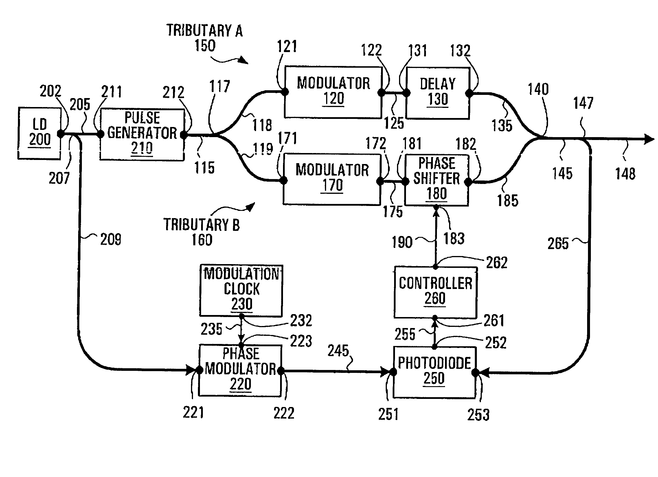
[0011]According to a second broad aspect, the invention provides for an apparatus for providing carrier suppression for the optical output of an optical time domain multiplexing (OTDM) module, the OTDM module having a tributary, the apparatus including a carrier phase shifter for shifting the phase of a carrier of an optical signal traversing the tributary of the OTDM module, and a feedback loop apparatus for controlling the carrier phase shifter, the feedback loop apparatus detecting a phase modulated portion of an original non-pulsed version of the carrier and a portion of the optical output, generating an electrical combined signal which corresponds to an envelope of the sum of the phase modulated portion of the original non-pulsed version of the carrier and the portion of the optical output, extracting an amplitude of an AC component of the electrical combined signal, and controlling a magnitude of the shifting of the phase of the carrier of the optical signal as a function of the amplitude to achieve a phase difference of π between successive pulses of the optical output.

Problems solved by technology

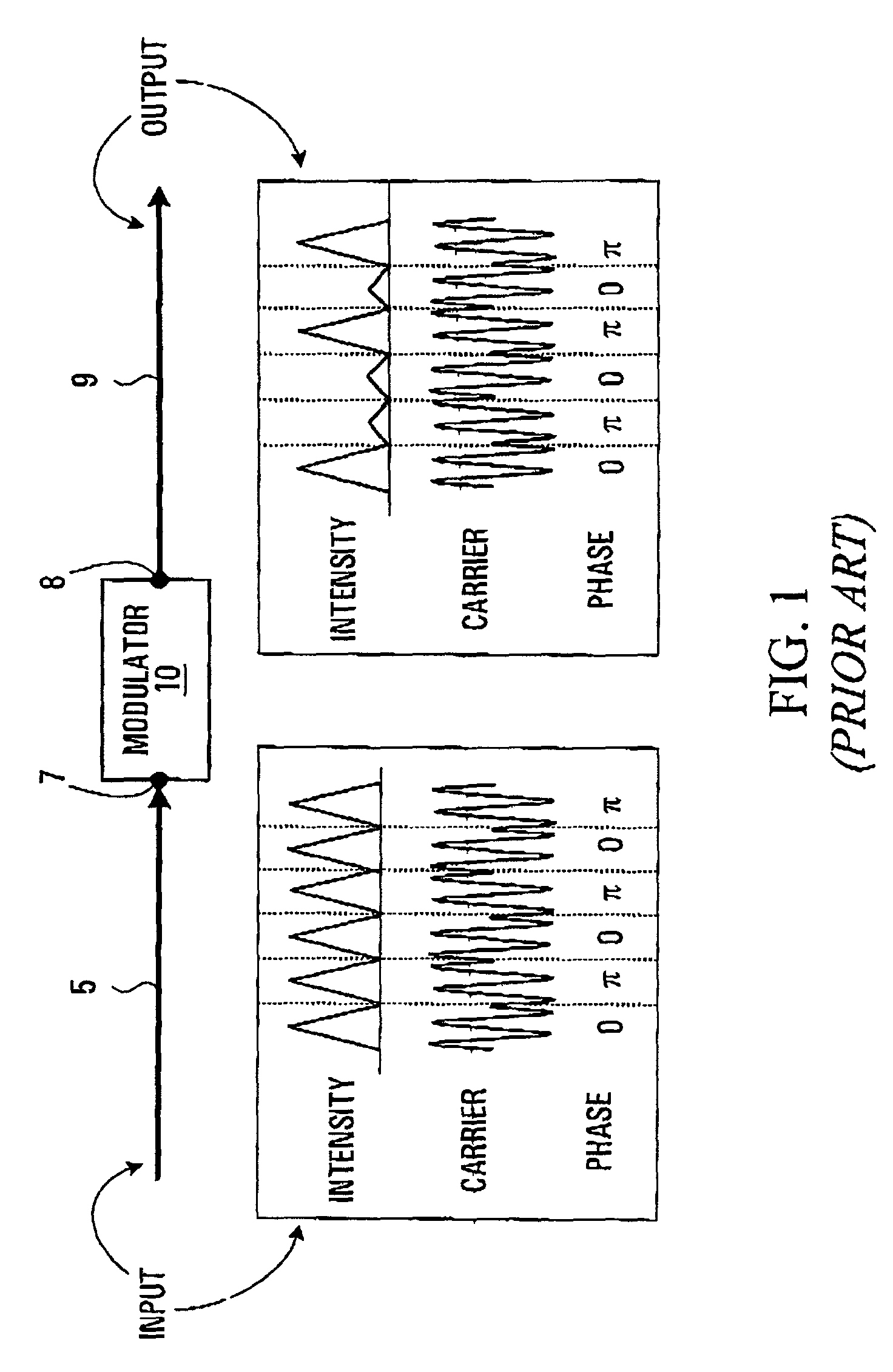
Traditionally, non-carrier suppressed optical signals do not compensate for neighboring pulse interaction, which arises when return to zero format data is simply encoded by a straight amplitude modulation or attenuation of the optical carrier without taking into account the phase of the carrier.
In fact, due to the nature of typical OTDM pulse multiplexing, the phase relationship between successive pulses is unknown and constantly changing due to changing environmental condition for example variations in temperature.
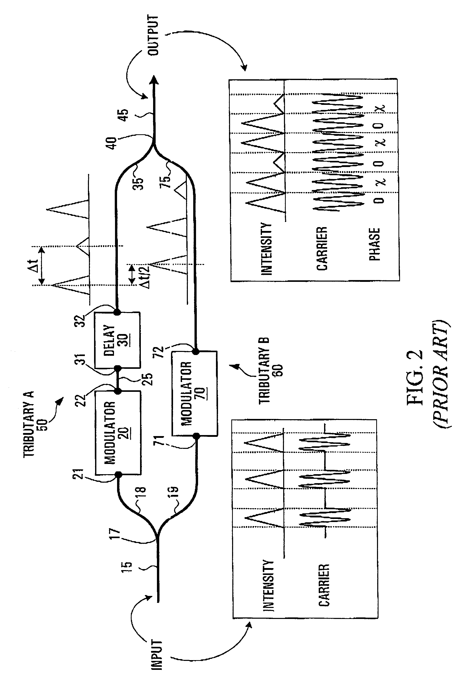
In conventional OTDM modules, it is very difficult to produce an optical path difference between two tributaries which is precisely some odd number of λ / 2.
The carrier phase difference between adjacent pulses is random and for practical purposes is unknown and unpredictable.

Method used


Image

  • Carrier-suppressed optical time domain multiplexing
  • Carrier-suppressed optical time domain multiplexing
  • Carrier-suppressed optical time domain multiplexing

Examples


Embodiment Construction

[0043]Referring to FIG. 3, an OTDM module for producing CS-RZ optical format signals constructed according the invention is described. The general method of carrier suppressed modulation is implemented on an OTDM module by locking the phase difference of pulses from the two tributaries to π, by way of adaptive phase shifting.

[0044]A preferred embodiment of an apparatus constructed according to the invention is now described in terms of its structure. An input optical signal which is made up of a pulse array propagates along an input waveguide portion 115. The input waveguide portion 115 is coupled to an optical splitter 117 which is set to split optical signals passing therethrough along two outputs in a preferably 50%-50% power ratio. A first output of the optical splitter 117 is coupled to a first upper waveguide portion 118. The first upper waveguide portion 118 is coupled to an input 121 of an upper optical attenuator or upper optical modulator 120. The upper optical attenuator ...


PUM


Abstract

A method and an apparatus for implementing carrier suppressed data format on conventional OTDM modules is provided. Adaptive phase shifting of optical signals traversing one of the tributaries of an OTDM module is performed with feedback loop control. A tapped portion of the input carrier signal is phase modulated at a frequency fc, and is combined with a tapped portion of the output from the OTDM. A phase shifter controller fed with this combined signal photodetects and band-pass filters the signal around fc to extract the amplitude of the AC component of the envelope of the combined signal, which depends upon the phase difference between successive pulses of the OTDM output. This signal is used to control a phase shifter coupled along one of the tributaries of the OTDM to adjust the phase difference of the signals of the two tributaries so that carrier suppression results.

Description

FIELD OF THE INVENTION[0001]The invention relates to optical time domain multiplexing and more particularly to phase control of the carrier of an optical time domain multiplexed signal.BACKGROUND OF THE INVENTION[0002]Optical time domain multiplexing is widely employed in high bit rate transmitter modules and is required for the use of modern components in systems with bit rates of 40 Gbps or higher. With increasing use of high bit rate components, optical systems are depending more and more on optical time domain multiplexing and its associated RZ (return to zero) data format. Improving the qualities of the data stream of high bit rate transmissions in RZ format is desirable and ever increasingly important.[0003]Traditionally, non-carrier suppressed optical signals do not compensate for neighboring pulse interaction, which arises when return to zero format data is simply encoded by a straight amplitude modulation or attenuation of the optical carrier without taking into account the...

Claims


Application Information

Patent Timeline
Patent Type & Authority Patents(United States)
IPC IPC(8): H04J14/08H04B3/10
CPCH04J14/08
Inventor FU, XIAOLIZHANG, GENZAOSHI, FENGWANG, TONGQINGLI, JINGHUI
Owner MOLEX INC
Learn More