
Audio apparatus

a piezoelectric transducer and audio technology, applied in the field of audio apparatus, can solve the problems of unfavorable pedestrian safety, adversely affecting the sensitivity and bandwidth of the apparatus, and less flexible mounting of the piezoelectric transducer in the one-part housing, so as to enhance pedestrian safety and improve the acoustic performance of the audio apparatus

Active Publication Date: 2009-07-21
GOOGLE LLC
View PDF16 Cites 32 Cited by
  • Summary
  • Abstract
  • Description
  • Claims
  • Application Information

AI Technical Summary

Benefits of technology

The invention is about an audio apparatus that uses a piezoelectric transducer to transmit sound to a user's inner ear. The apparatus has a soft casing and a hard housing that form a cavity between them. This design provides flexibility in design and allows for a more flexible and comfortable fit on the user's pinna. The soft material in the casing helps to protect the transducer and minimize unwanted radiation. The coupling between the casing and the housing is minimal to reduce vibration and unwanted radiation. The mechanical properties of the transducer are matched to the pinna to improve efficiency and bandwidth. The apparatus is designed to be comfortable and secure on the user's pinna.

Problems solved by technology

In contrast, mounting a piezoelectric transducer in a one-part housing is less flexible.
If a relatively hard material is used this may adversely affect the sensitivity and bandwidth of the apparatus and may lead to unwanted radiation.
However, if a relatively soft material is used, the apparatus may not be sufficiently robust.

Method used


Image

  • Audio apparatus
  • Audio apparatus
  • Audio apparatus

Examples


Embodiment Construction

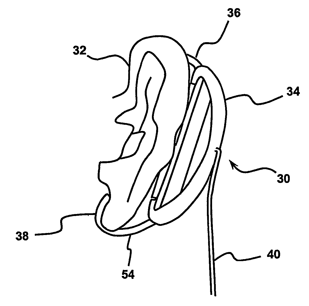
[0045]FIG. 1 shows an audio apparatus 30 according to the present invention mounted on a pinna 32. The apparatus comprises a protective outer housing 34 to which coupling means 54 having upper and lower hooks 36,38 are attached. The hooks 36,38 loop over the upper and lower parts of the pinna 32 respectively to ensure a good contact between the apparatus and the pinna. Leads 40 extend from the housing 34 to be connected to an external sound source.

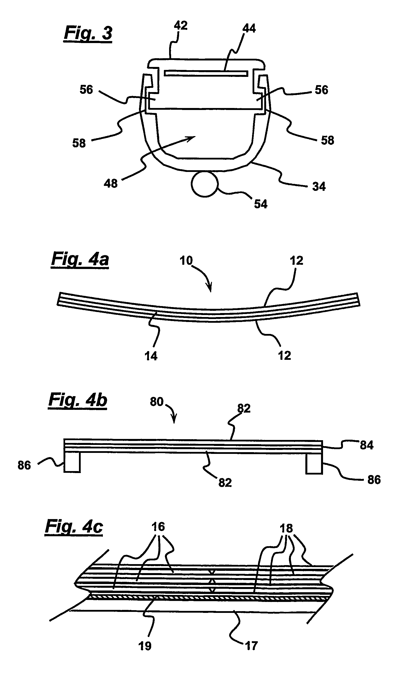
[0046]As shown in FIGS. 2 and 3, the outer housing 34 is a hollow body which houses a casing 42 in which a piezoelectric transducer 44 is embedded. A cavity 48 is defined between the inner face of the outer housing 34 and the outer face of the casing 42. The casing 42 is of generally rectangular cross-section with a concave section 46 and is shaped so as to provide a snug fit on the user's pinna. The casing 42 is formed from a material which is much softer that the material used for the housing 34.

[0047]The outer housing 34 is connected to...


PUM


Abstract

Audio apparatus (30) comprising a piezoelectric transducer (44) and coupling means (54) for coupling the transducer to a user's pinna (32) whereby the transducer excites vibration in the pinna (32) to cause it to transmit an acoustic signal from the transducer (44) to a user's inner ear, characterised in that the transducer is embedded in a casing (42) of relatively soft material and the casing (42) is mounted to a housing (34) of relatively hard material such that a cavity (48) is defined between the casing (42) and housing (34). A method of designing audio apparatus comprising mechanically coupling a piezoelectric transducer to a user's pinna and driving the transducer so that the transducer excites vibration in the pinna to cause it to transmit an acoustic signal from the transducer to a user's inner ear, characterised by embedding the transducer in a casing of relatively soft material and by mounting the casing to protective housing of relatively hard material such that a cavity is defined between the casing and housing.

Description

[0001]This application claims the benefit of U.S. provisional application No. 60 / 501,425, filed Sep. 10, 2003.TECHNICAL FIELD[0002]The invention relates to audio apparatus and more particularly to audio apparatus for personal use.BACKGROUND ART[0003]It is known to provide earphones which may be inserted into a user's ear cavity or headphones comprising a small loudspeaker mounted on a headband and arranged to be placed against or over the user's ear. Such sound sources transmit sound to a user's inner ear via the ear drum using air pressure waves passing along the ear canal.[0004]A typical conventional earphone uses a moving coil type transducer mounted in a plastic housing. The moving coil is connected to a light diaphragm which is designed to fit into the entrance of the ear canal. The moving coil and diaphragm are light and are coupled intimately to the eardrum at the other end of the ear canal. The acoustic impedance of the eardrum and ear canal seen by the moving coil transduce...

Claims


Application Information

Patent Timeline
Patent Type & Authority Patents(United States)
IPC IPC(8): H04R25/00H04R1/10
CPCH04R1/1075H04R1/1008H04R1/105H04R2460/13H04R17/00H04R1/10
Inventor AZIMA, HENRYHILL, NICHOLAS PATRICK ROLANDCROSS, ROBIN CHRISTOPHERWHITWELL, TIMOTHY CHRISTOPHERVAN DER LINDE, JOHAN FRANK
Owner GOOGLE LLC
Learn More