
Tire pressure monitoring system plant learning

a technology of tire pressure monitoring and plant learning, applied in the field of system and method for teaching identification information to a receiver, can solve problems such as unsatisfactory confusion between vehicles and sensors

Inactive Publication Date: 2009-07-21
CONTINENTAL AUTOMOTIVE SYST INC
View PDF6 Cites 7 Cited by
  • Summary
  • Abstract
  • Description
  • Claims
  • Application Information

AI Technical Summary

Benefits of technology

[0010]In one example method and system, the low frequency antenna provides and sends a code signal that provides an identification of the location of the tire pressure monitoring sensor. The tire pressure monitoring sensor then in turn relays this code to the receiver. In this system several receivers may be disposed substantially adjacent to each other. However, each receiver is set up to recognize and process only those transmissions with a specific location identification identifier code. In this example each of the receivers are set to receive transmissions of the same frequency. The difference being that each adjacent receiver corresponds with a unique adjacent low frequency antenna. Each antenna transmits a separate or different identification code such that the receiver will only receive transmissions from tire pressure monitoring systems that have been prompted by the corresponding low frequency antenna. In this way receipt of transmissions from tire pressure monitoring sensors on other vehicles is prevented.
[0011]Another example system includes three receivers all set to receive transmissions at different frequencies. Corresponding low frequency antennas to these receivers transmit instructions that cause each of the tire pressure monitoring sensors to transmit the initialization signal at a different frequency corresponding with the receiver that in turn corresponds with the specific location. Each of the tire pressure monitoring sensors is equipped with a fractional phase loop circuit that provides for the transmission at different frequencies. In this example system, each of the receivers is set to receive signals of different frequencies therefore it is substantially prevented from receiving transmissions from tire pressure monitoring sensors disposed on vehicles not corresponding with the receivers specific location.
[0013]Accordingly, the system and method of this invention provides for the initial learning of the tire pressure monitoring sensor identification codes by a vehicle receiver without errant learning of incorrect sensor identifiers.

Problems solved by technology

Disadvantageously, any transmission from the sensors is broadcast throughout a wide area, such that adjacent and separate receivers from different systems or vehicles may also receive the identification code and undesirably record that identification code as belonging to that particular vehicle or system.
Such confusion between vehicles and sensors is not desirable.

Method used


Image

  • Tire pressure monitoring system plant learning
  • Tire pressure monitoring system plant learning
  • Tire pressure monitoring system plant learning

Examples


Embodiment Construction

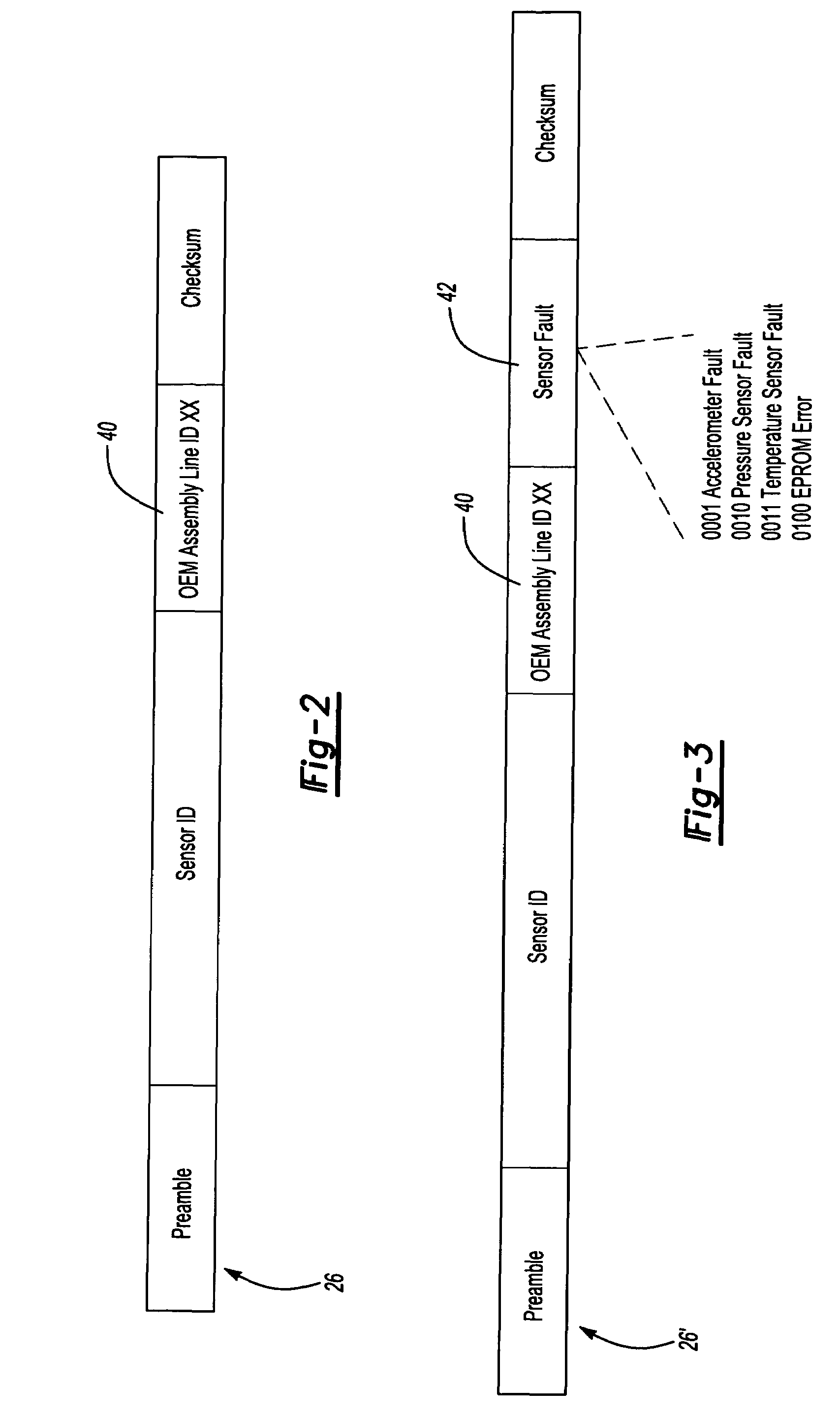
[0019]Referring to FIG. 1, an example system 10 for teaching tire pressure monitoring sensor identification codes to a vehicle receiver includes a receiver 18 that receives signals 26 from a tire pressure monitoring sensor 28. The tire pressure monitoring sensor 28 sends a signal in response to a prompt signal.24 sent by a low frequency antenna 12. The initialization signal 26 includes a unique identification code that is specific to that tire pressure monitoring sensor 28. This specific identification code is received by a receiver 18 that is disposed within the plant. The receiver 18 disposed within the plant communicates these identification codes to a vehicle receiver 30 that is disposed within the vehicle. Once the initial identification codes are saved and stored within the vehicle receiver 30 operation and the signals from the tire pressure monitoring sensors 28 will be recognized by that receiver 30. The receiver 30 will ignore signals from all other tire pressure monitoring...


PUM


Abstract

A method and system of teaching identification codes for a tire pressure monitoring system includes the steps of transmitting a prompt signal that includes a location identifier. This prompt signal instructs the tire pressure monitoring sensor to transmit an initialization signal. The initialization signal includes the location identifier. A factory receiver is set up to recognize transmissions that include a corresponding location identifier. The receiver disregards all other transmissions that do not include the corresponding desired location identifier.

Description

CROSS REFERENCE TO RELATED APPLICATION[0001]The application claims priority to U.S. Provisional Application Nos. 60 / 729,025 and 60 / 738,362 which were filed on Oct. 21, 2005.BACKGROUND OF THE INVENTION[0002]This invention generally relates to system and method for teaching identification information to a receiver for devices that communicate through radio frequencies. More particularly, this invention relates to a system and method for teaching and verifying identification information for systems that initialize a communication link between a remote radio frequency communication device and a receiver.[0003]Remote activation and sensor devices communicate with a receiver that is programmed to recognize a specific remote activation device. The initial programming of such remote activation devices requires that a unique identifier of the remote device be communicated and stored within the receiver for future reference. During operation, the receiver interrogates incoming transmissions f...

Claims


Application Information

Patent Timeline
Patent Type & Authority Patents(United States)
IPC IPC(8): B60C23/04
CPCB60C23/0481B60C23/0408
Inventor DENIAU, JEAN-CHRISTOPHEWALLACE, MARK D.
Owner CONTINENTAL AUTOMOTIVE SYST INC
Learn More