
Electrical contact having asymmetric dual-contact-engaging-arm

a dual-contact, electrical connection technology, applied in the direction of fixed connections, coupling device connections, engagement/disengagement of coupling parts, etc., can solve the problems of introducing excess parts and manufacturing costs, certain risks of opening in some conducting path between the processor and the socket, and achieve the effect of reducing impedance, preventing contacts from undesired shorts, and reliable electrical connections

Inactive Publication Date: 2009-07-21
HON HAI PRECISION IND CO LTD
View PDF15 Cites 45 Cited by
  • Summary
  • Abstract
  • Description
  • Claims
  • Application Information

AI Technical Summary

Benefits of technology

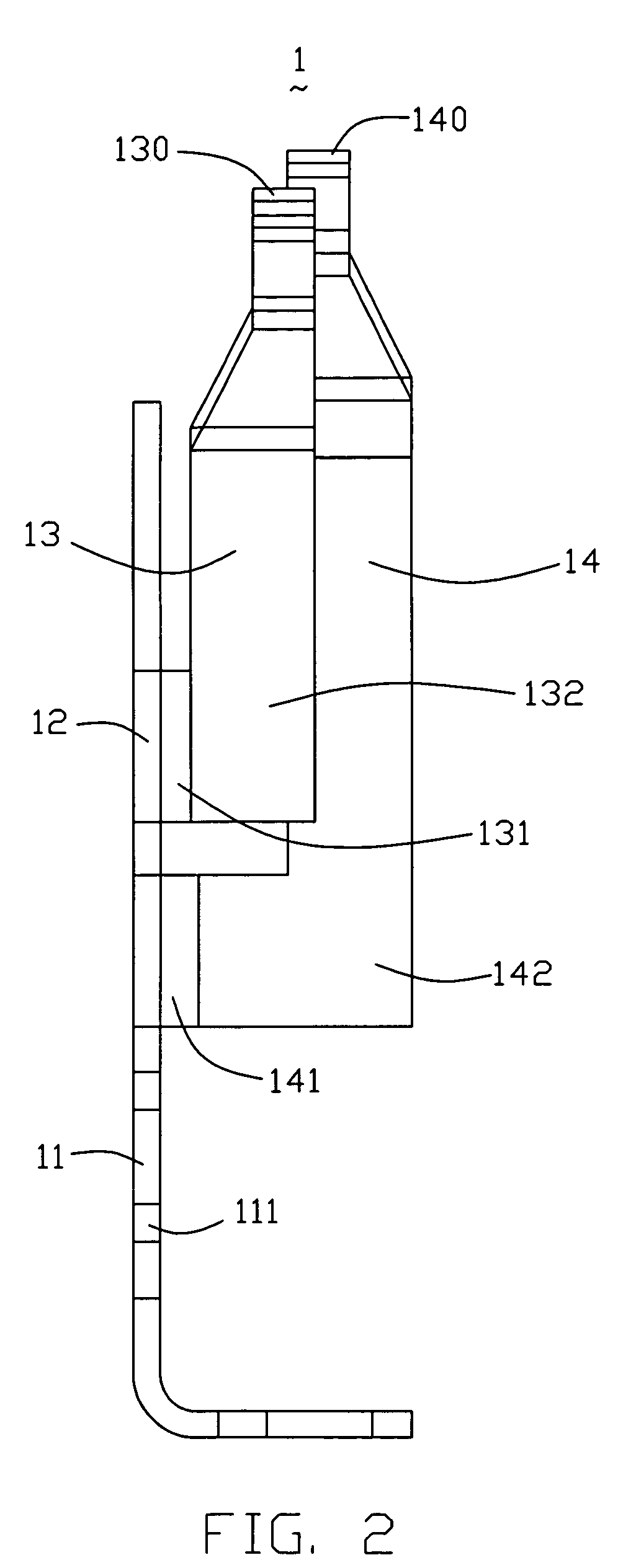
The present invention provides a contact terminal with two contact arms for reliable electrical connection and reducing impedance. The contact terminal is designed to prevent contacts from undesired short caused by touching of adjoining contacts while an integrated circuit is mounted in the socket. The contact terminal includes a support body, first and second contact arms, first and second linking arms, and different projecting heights respectively measured from free ends of the first and second contact arms to a plane coplanar with the support body. The contact terminal is securely held in a hole of an land grid array (LGA) socket with interfering sections. The technical effects of the invention include reliable electrical connection, reducing impedance, and preventing short circuits.

Problems solved by technology

This PGA base and cover arrangement, however, requires use of a mechanism, such as a lever assembly, thereby introducing excess parts and manufacturing cost.
These drawbacks are especially troublesome in applications where space is at a premium, such as on motherboards for desktop and laptop computers.
However, the contacts in existing LGA socket have only one contact portion to electrically connect with pads of the processor.
As a result, there are certain risks of opening in some conducting path between the processor and the socket while the processor is mounted in the LGA Socket.
At the same time, a single conducting path would result in high impedance as well against the application of high power connectors.

Method used


Image

  • Electrical contact having asymmetric dual-contact-engaging-arm
  • Electrical contact having asymmetric dual-contact-engaging-arm
  • Electrical contact having asymmetric dual-contact-engaging-arm

Examples


Embodiment Construction

[0030]While the invention may be susceptible to embodiment in different forms, there is shown in the drawings, and herein will be described in detail, a specific embodiment with the understanding that the present disclosure is to be considered an exemplification of the principles of the invention, and is not intended to limit the invention to that as illustrated and described herein.

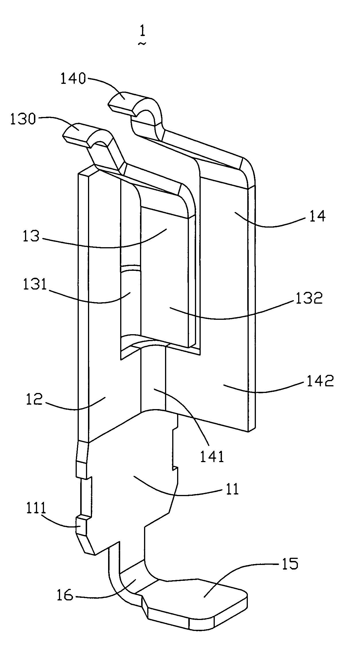
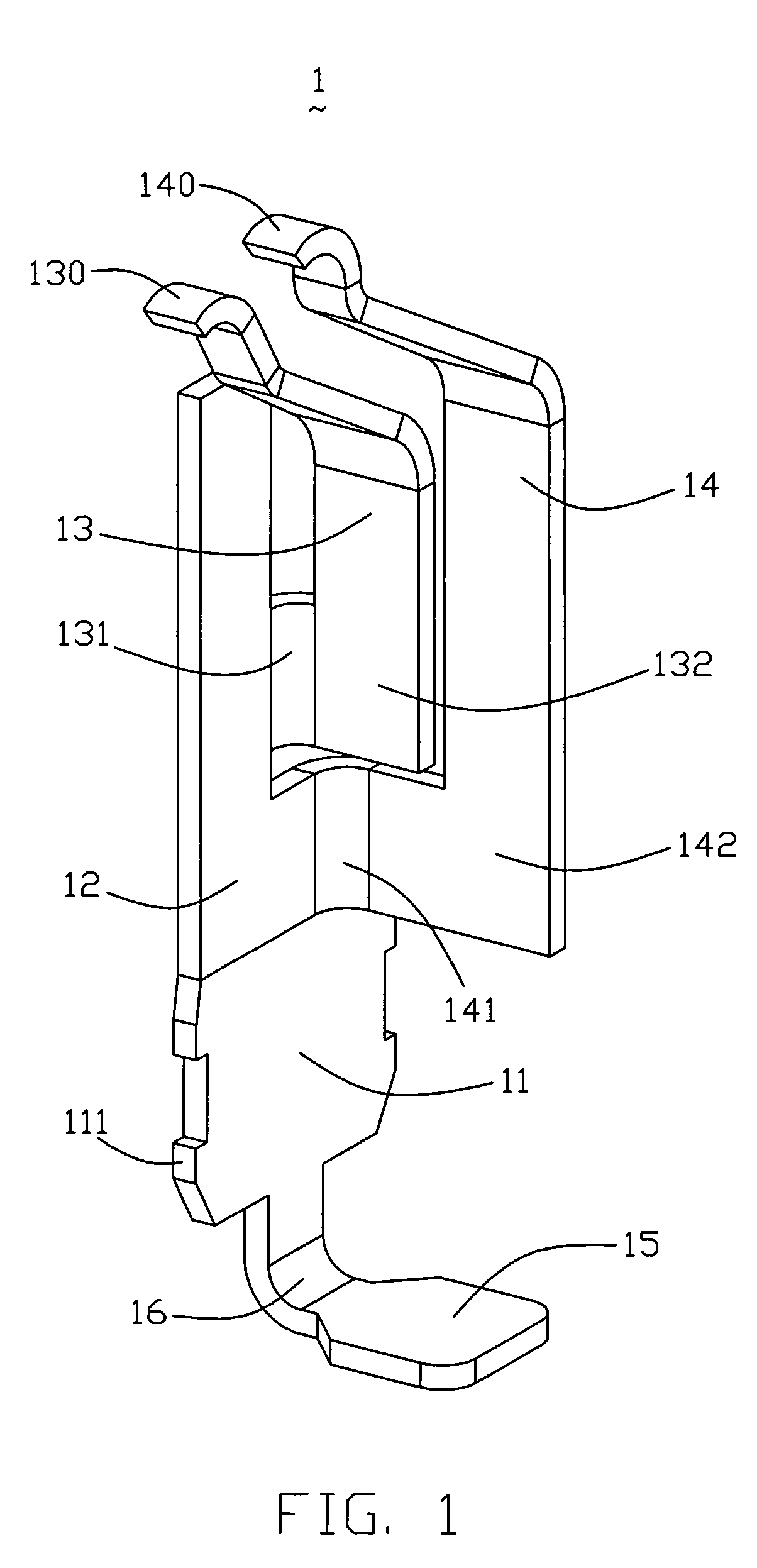
[0031]FIG. 1 illustrates an isometric view of a land grid array (LGA) contact terminal 1 formed in accordance with one embodiment of the present invention. The LGA contact terminal 1 is made of metal and has a base portion 11 with barbs 111 on two opposite sides to form a retaining portion for holding the LGA contact terminal 1 in a hole of an insulating housing (not shown). An engaging portion 12 upwardly extends from an upper section of the base portion 11. A first contact arm13 extends upward from a first portion of the engaging portion 12, and a second contact arm 14 extends upward from a second port...


PUM


Abstract

A contact (1) is provided for use in a land grid array (LGA) socket (300). The contact (1) of the present invention comprises a support body (12), a first contact arm (13) and a second contact arm (14) respectively extend from the same lengthwise side of the supporting body (12) through a first curved arm (131) and a second curved arm (141), a plurality of barb (111) configured in the support body (12) are adapted to securely hold the contact (1) in a hole (202) of a insulative housing. The two contact arms (13), (14) with different length are parallel one another and not aligned in the same plane for preventing contacts from undesired short caused by touching of adjoining contacts while an integrated circuit is mounted in the socket.

Description

BACKGROUND OF THE INVENTION[0001]1. Field of the Invention[0002]The present invention generally relates to an electrical connector, and more particularly to a socket connector having a plurality of contact terminals, each of the contact terminals includes a pair of contact arms both adapted for reliably ensuring electrical connection between a circuit board and a corresponding conductive pad of a processor.[0003]2. Description of Related Art[0004]As the rapid development of electronic technology, the speeds of computers are becoming faster and faster for complying with the public's requests on processing and transfer of huge amount of data, such as image data or three dimensional data. A heart of a computer is a computer processor. The processor is always in a constant state of technical innovation. As the speed of the processor increases, it becomes increasingly important for all the components in the data processing path to become faster in order to prevent data congestion or “bot...

Claims


Application Information

Patent Timeline
Patent Type & Authority Patents(United States)
IPC IPC(8): H01R12/00H01R12/57
CPCH01R12/88H01R13/2492H01R12/57
Inventor LIU, JIA-HAUHSIEH, FU-PIN
Owner HON HAI PRECISION IND CO LTD
Learn More