
MRI system having implantable device safety features

a technology of implantable devices and safety features, which is applied in the field of implantable medical devices, can solve problems such as problems such as problems with implantable medical devices, crm devices, and power supplies of some implantable devices

Inactive Publication Date: 2009-07-14
CARDIAC PACEMAKERS INC
View PDF299 Cites 117 Cited by
  • Summary
  • Abstract
  • Description
  • Claims
  • Application Information

AI Technical Summary

Benefits of technology

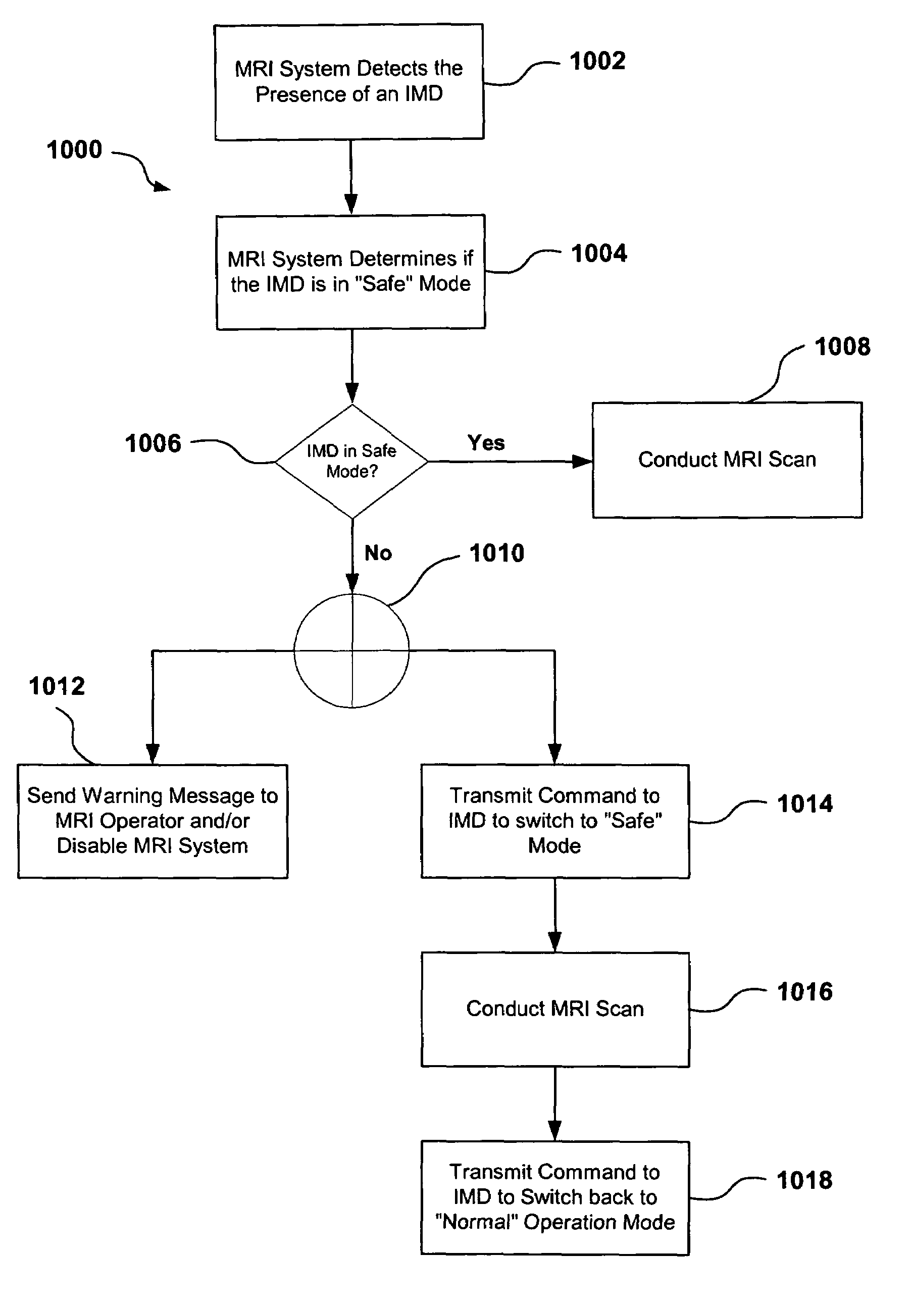
[0011]In another embodiment of the invention, the IMD can be operable to detect a magnetic field produced by the MRI system. In accordance with this embodiment, the telemetry device can be configured to receive a command from the IMD instructing the telemetry device that an IMD is present and not in an MRI-safe mode. The telemetry device then can communicate this information to the MRI system, preventing the MRI system from conducting an MRI scan.

Problems solved by technology

These strong electromagnetic fields produced by MRI systems can cause problems for implantable medical devices, such as CRM devices.
For example, the static magnetic field can affect the magnetically controlled (reed) switch that prevents inappropriate programming of a pulse generator (“PG”), and in some cases, it can saturate the core of inductive switching power supplies, causing difficulties for some implantable device power supplies.
Further, the time-varying gradient field can generate significant voltage in CRM device leads, which can cause false cardiac event sensing.
Finally, some tests have shown that the RF field produced in MRI systems can cause CRM device heating, and voltage generation in the CRM device circuitry and leads.
Of particular concern are the MR-induced voltages, which potentially can inhibit pacing and / or ICD defibrillation, or which can induce excessively rapid pacing and / or inappropriate ICD defibrillation shocks.
Both of these malfunctions can be life-threatening events.
Indeed, some deaths have been reported for patients with implanted CRM systems who were inadvertently subjected to MRI scans.
MRI fields can adversely affect other IMDs, as well.

Method used


Image

  • MRI system having implantable device safety features
  • MRI system having implantable device safety features
  • MRI system having implantable device safety features

Examples


Embodiment Construction

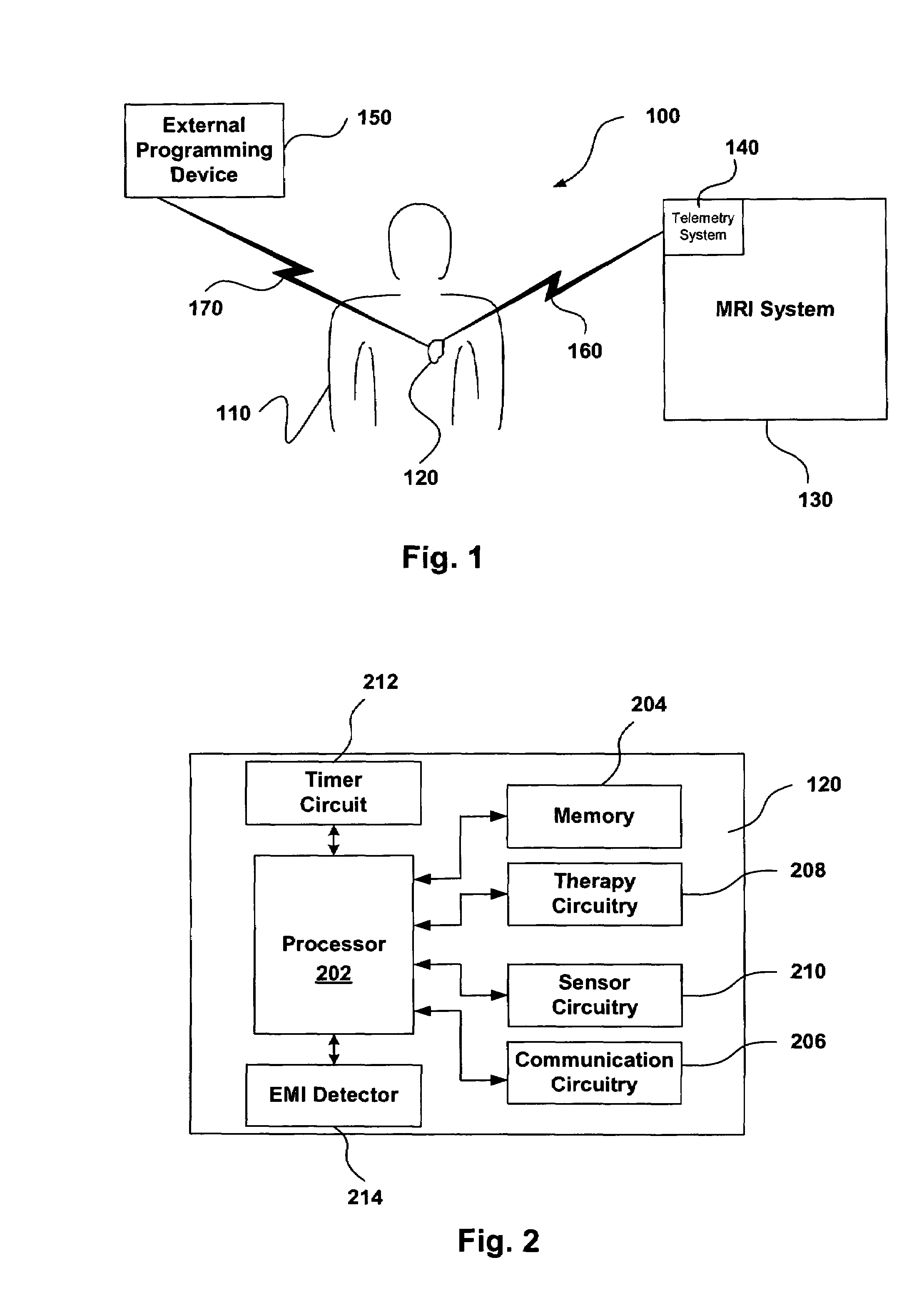
[0019]The present invention relates generally to magnetic resonance imaging (“MRI”) systems and implantable medical devices (“IMDs”), and more particularly to systems, devices and methods for rendering IMDs more safe in the presence of strong electro-magnetic interference (“EMI”), such as those produced by MRI systems. In accordance with at least some embodiments, the present invention relates to IMDs that can be programmed to alter their operational modes in the presence of electro-magnetic interference to prevent damage to the IMD and / or the patient. As discussed in more detail below, the IMDs can be programmed from an external programming device, or the IMDs can be configured to automatically change operational modes in the presence of the EMI.

[0020]As used herein, the term electro-magnetic interference (“EMI”) can refer to any EMI, such as static magnetic fields, gradient magnetic fields, and / or radio frequency (“RF”) fields generated by an MRI system, or any other electro-magne...


PUM


Abstract

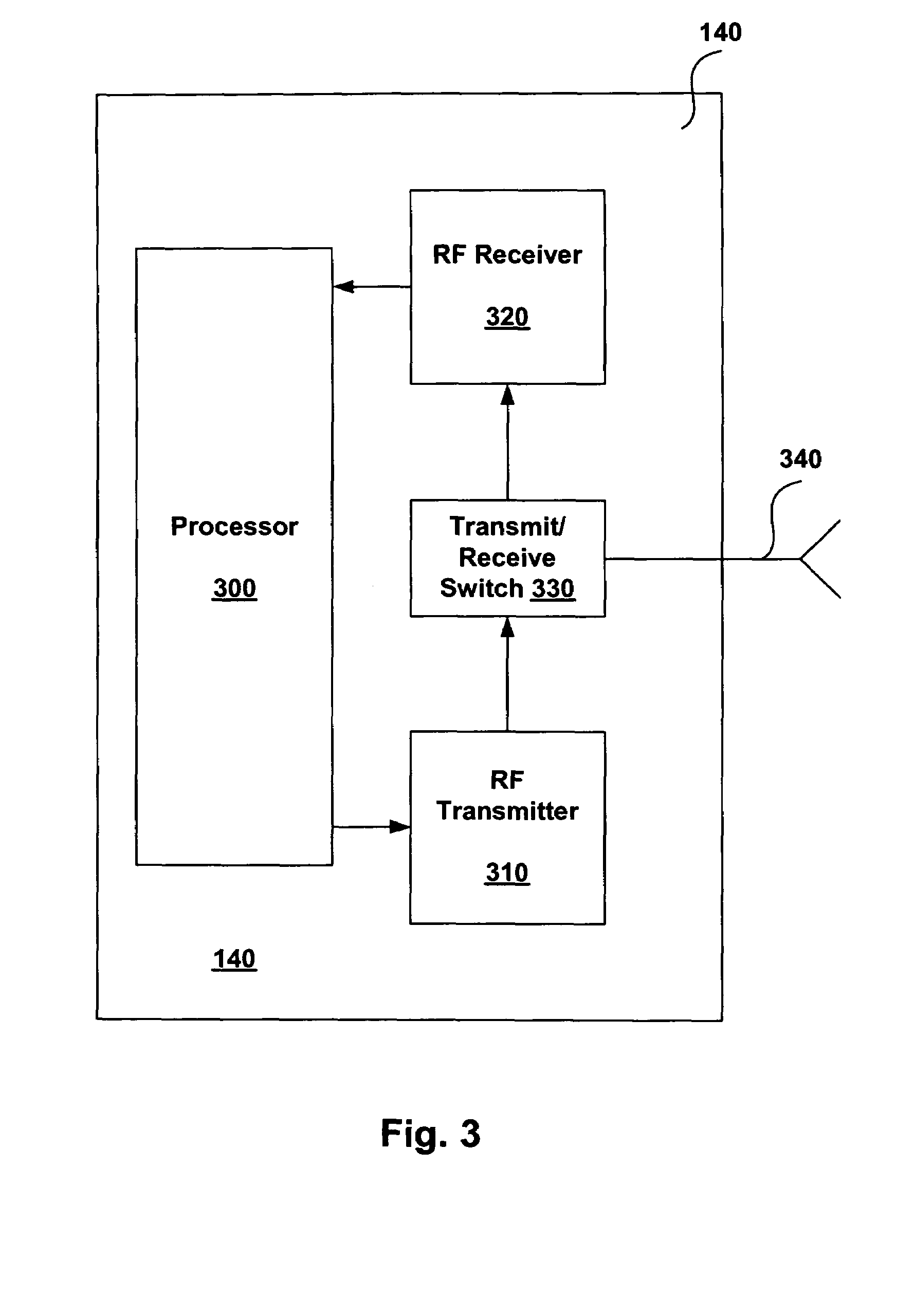
One embodiment of the present invention relates to a telemetry device which is in communication with an MRI system, and which is operable to communicate with an implantable medical device (IMD). The telemetry device includes a controller and telemetry circuitry. In one embodiment, the telemetry device is operable to automatically detect the presence of an IMD, and determine if the IMD is in an MRI-safe mode. If the IMD is not in an MRI-safe mode, the telemetry device can initiate processing to prevent the MRI system from conducting an MRI scan while the IMD in not in an MRI-safe mode.

Description

BACKGROUND OF THE INVENTION[0001]The present invention relates generally to implantable medical devices (“IMDs”) and magnetic resonance imaging (“MRI”) systems, and more particularly to systems, devices and methods for rendering IMDs more safe in the presence of strong electro-magnetic interference, such as those produced by (“MRI”) systems.[0002]IMDs can be used to provide a number of different medical therapies to patients. For example, therapeutic IMDs can include pacemakers, implantable cardioverter defibrillators (“ICDs”), blood pumps, drug delivery devices, neurostimulating devices, and the like. Some of the most common IMDs include pacemakers and ICDs (collectively referred to as cardiac rhythm management (“CRM”) devices), which are used to control the heart rate when heart rhythm disorders occur.[0003]Magnetic resonance imaging (MRI) is an efficient technique used in the diagnosis of many disorders, including neurological and cardiac abnormalities and other diseases. MRI has...

Claims


Application Information

Patent Timeline
IPC IPC(8): A61N1/37
CPCA61B5/055A61N1/37A61N1/37264A61N1/3718
Inventor COOKE, DANIEL J.VON ARX, JEFFREY A.
Owner CARDIAC PACEMAKERS INC
Learn More