
Educational electrical generation kit

a technology of electrical generation and educational displays, applied in the field of educational displays, can solve the problems of limited utility of displays, failure to capture the attention of many viewers, and troublesome setup and teardown efforts

Inactive Publication Date: 2009-07-14
HOFFMANN GREGORY C
View PDF17 Cites 46 Cited by
  • Summary
  • Abstract
  • Description
  • Claims
  • Application Information

AI Technical Summary

Benefits of technology

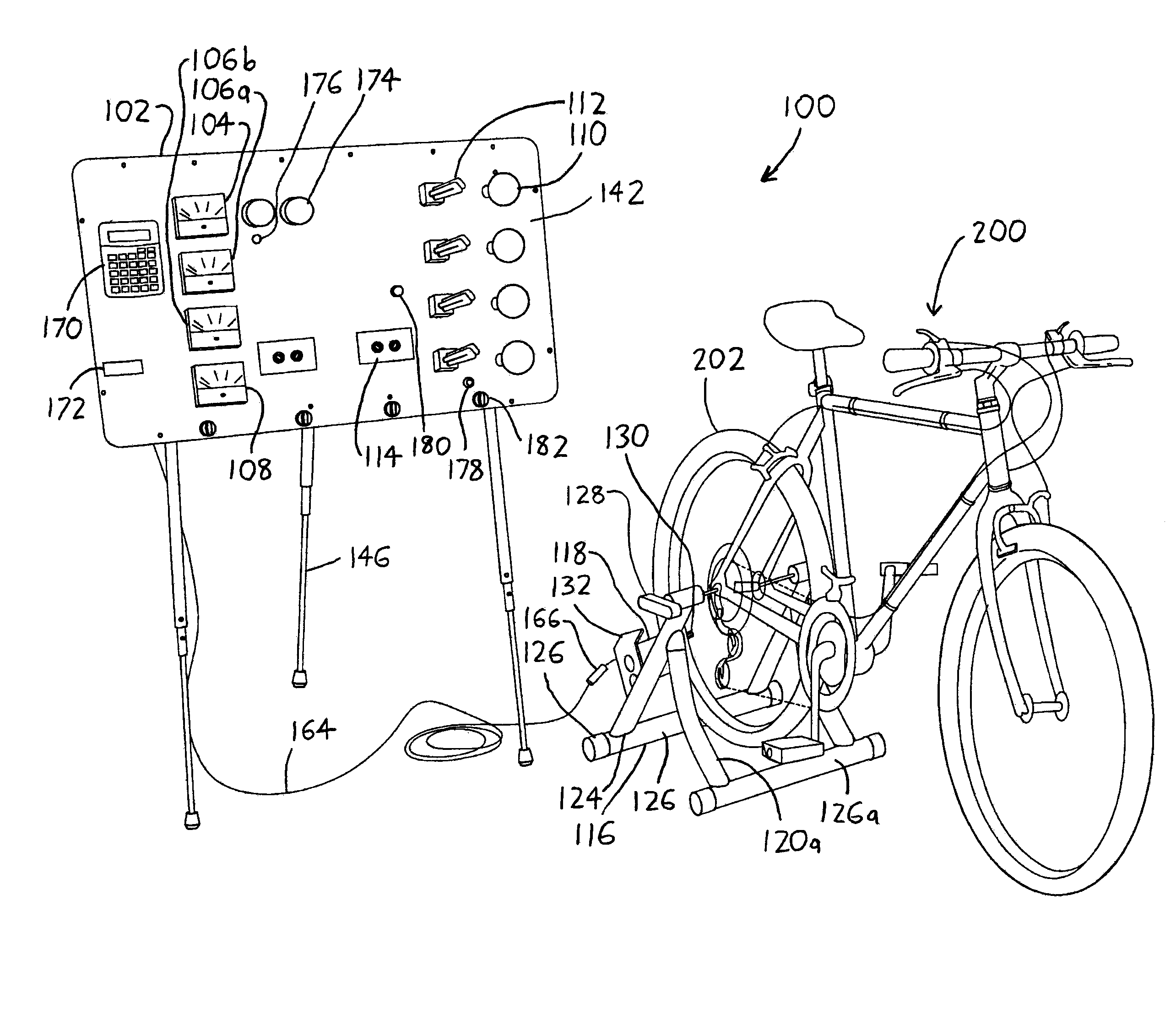
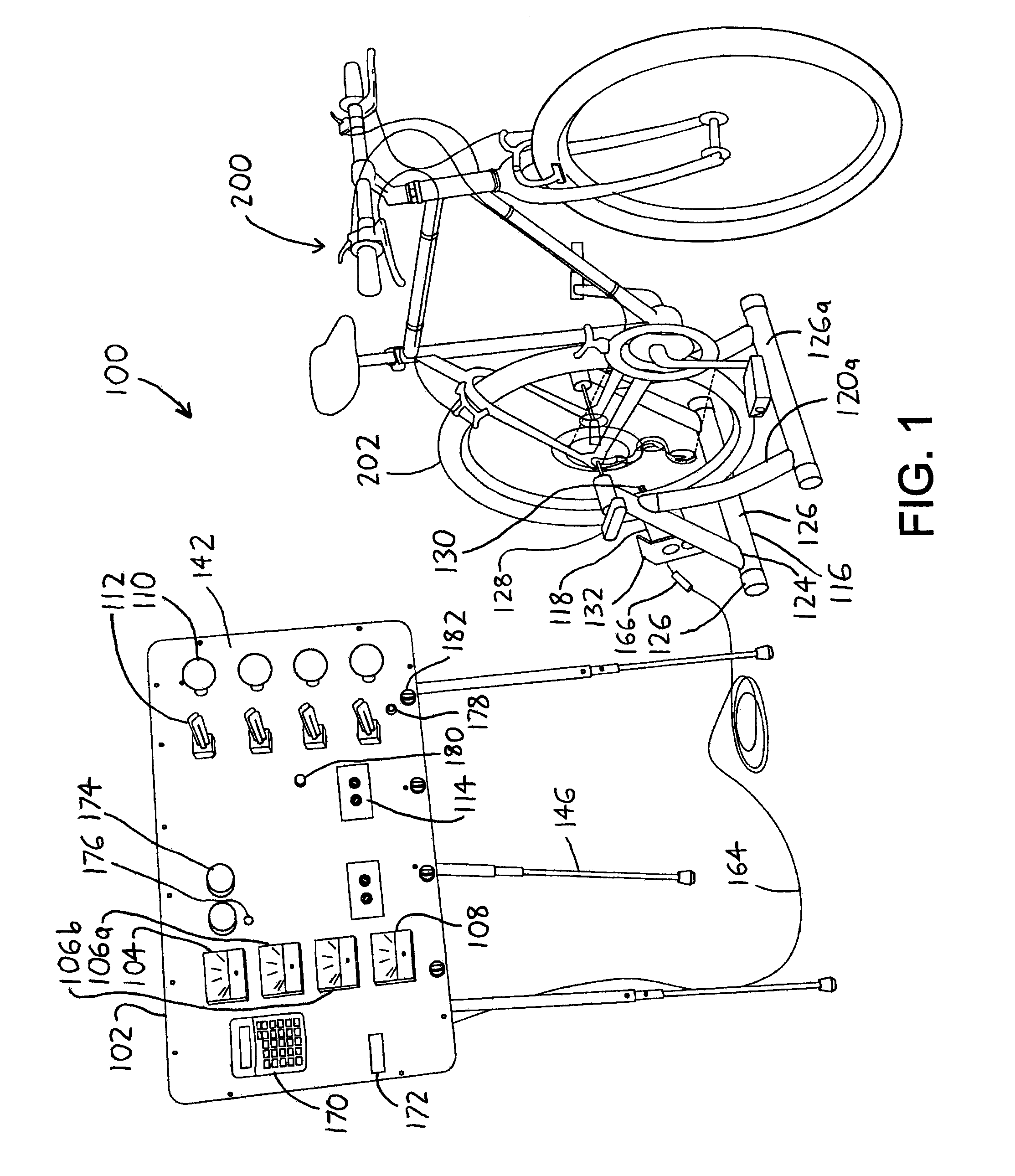
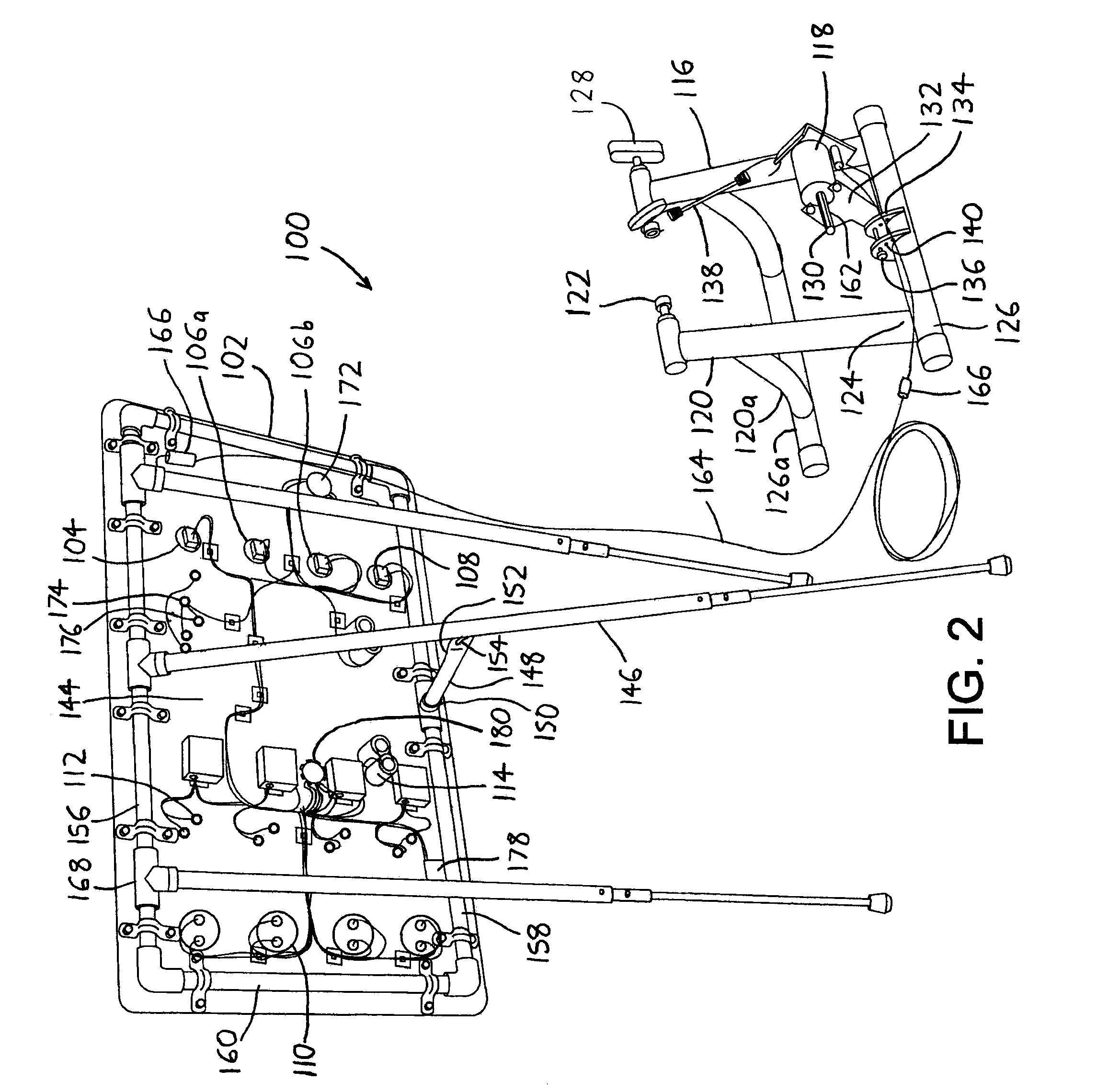
[0008]The generator 118 is affixed to the bicycle wheel support 116 so that when a bicycle wheel 202 is engaged between the axle engagements 122, the bicycle wheel 202 will engage (ride against) the protruding generator shaft 130 of the generator 118 so that driving the bicycle wheel 202 will power the generator 118. To allow the generator 118 to engage bicycle wheels 202 of different diameters, the generator 118 is preferably situated on a generator mount 132 which is pivotally affixed with respect to the bicycle wheel support 116. This pivotable mounting allows the axis of the generator shaft 130 to travel in an arc intersecting the circumference of any bicycle wheel 202 engaged within the axle engagements 122, and to deflect to accommodate bicycle wheels 202 having different diameters. As shown in FIG. 2, this can be accomplished by providing a bridge member 134 which extends upwardly from the support base 126, and then providing a generator adjustment rod 136 which extends from the bridge member 134 along a generator adjustment axis parallel to the bicycle axle axis (as defined between the axle engagements 122). The generator mount 132 can then be formed as a simple cradle or yoke which holds the generator 118, and which pivots about the generator adjustment rod 136. As a result, the generator 118 orbits a generator adjustment axis defined by the generator adjustment rod 136 so that the generator shaft 130 may be adjustably respaced with respect to a bicycle wheel 202 resting between the axle engagements 122. The generator mount 132 is then preferably elastically biased toward the bicycle axle axis (as defined between the axle engagements 122) so that the generator shaft 130 is urged into engagement with any bicycle wheel 202 resting between the axle engagements 122, and this can simply be effected by providing an elastic member 138 (such as a bungee cord) between the generator mount 132 and the bicycle wheel support 116. To allow the pivotable generator 118 further ability to accommodate differently sized and / or configured bicycle wheels 202, the generator mount 132 is also preferably translatable along the generator adjustment axis (as by having the generator adjustment rod 136 axially repositionable within the bridge member 134, and / or by having the generator mount 132 respositionable along the generator adjustment rod 136), thereby allowing the generator 118 to be moved to one side to accommodate wider bicycle wheels 202. Additionally, to better accommodate bicycle wheels 202 having very small or very large diameters, the bridge member 134 preferably bears multiple adjustment rod apertures 140, whereby the generator adjustment rod 136 may be fit into a selected one of the adjustment rod apertures 140 to allow the generator mount 132 to pivot about a selected generator adjustment axis.
[0012]The foregoing arrangement allows the display board 102 to have its board support legs 146 telescopically collapsed and folded against the display board 102, and compactly transported to a school or other demonstration site along with the bicycle wheel support 116. The display board 102 may then be erected and connected to the generator 118 of the bicycle wheel support 116, which may have the bicycle 200 of a participant installed by inserting the axle of the (driven) bicycle wheel 202 into the axle engagements 122 with the bicycle wheel riding against the generator shaft 130 (which is shown bearing teeth 162, see FIG. 2, for better engagement with the bicycle wheel). Owing to the pivoting (and translatable) mounting of the generator mount 132, the generator shaft 130 will deflect to accommodate bicycle wheels 202 of virtually any size, with the elastic member 138 (FIG. 2) holding the generator shaft 130 against the wheel. (Note that the use of a removable bungee cord as the elastic member 138, with the bungee cord 138 hooked about an axle engagement 122 and extending downwardly to the generator mount 132, allows the elastic member 138 to be installed after the wheel of the bicycle 200 is installed between the axle engagements 122, thereby preventing the elastic biasing of the generator mount 132 and its generator 118 from interfering with the installation of the bicycle wheel.) The participant may then pedal his / her bicycle 200 to power the generator 118, and an operator (or the participant on the bicycle 200) may monitor his / her output on the display board 102, switch between different loads or other components on the display board 102, add new / different loads to different sockets 114, etc. Since the display board 102 is human-powered, observers are provided with a better notion of the work needed to generate the power required to operate common loads.

Problems solved by technology

Such displays may be viewed by multiple people at the same time, but because of their lack of interactivity, they fail to capture the attention of many viewers.
Thus, in both of the foregoing cases, the displays have limited utility since they cannot easily be transported from place to place—e.g., to different classrooms, museums, and exhibitions and other public events—and / or require significant setup and teardown efforts even when they can be transported.
Also, in both of the foregoing cases, while the displays can illustrate the cost of electrical power to some degree, these teachings do not carry significant impact since the displays simply use batteries, electrical wall sockets, or other readily-available power supplies, which do little to impart appreciation of the true effort needed for electrical power generation.

Method used


Image

  • Educational electrical generation kit
  • Educational electrical generation kit
  • Educational electrical generation kit

Examples


Embodiment Construction

[0016]To elaborate on the discussion above, following are further details regarding the preferred exemplary version of the electrical generation kit 100 illustrated in the drawings, as well as selected modifications that can be made to the kit 100.

[0017]The bicycle wheel support 116 may be capable of folding into a compact configuration, with the supplementary support legs 120a and supplementary support base 126a being pivotable on the support legs 120 to unfold to the position illustrated in the drawings (at which point they might be prevented from unfolding further without encountering interference). Thus, along with the pivotable generator mount 132, the bicycle wheel support 116 can be folded into a relatively flat state and can be stowed in a carrying case / suitcase along with the display board 102 for easy transport. The bicycle wheel support 116 is preferably made out of steel or other metals for sake of strength, though it could be made of composite or plastic materials inste...


PUM


Abstract

An educational electrical generation kit includes a bicycle wheel support which may accommodate the driven wheel of a bicycle, and wherein a generator engages the driven bicycle wheel to generate electricity. The kit also includes a display board with various electrical output meters and / or electrical loads for monitoring and / or dissipating the electrical output from the bicycle. The kit is designed to be readily portable and easily set up and torn down, and to allow a spectator / participant to incorporate a bicycle of virtually any size into the bicycle wheel support to interactively generate electricity for use in the display board.

Description

CROSS-REFERENCE TO RELATED APPLICATIONS[0001]This application claims priority under 35 USC §119(e) to U.S. Provisional Patent Application 60 / 693,340 filed 22 Jun. 2005, the entirety of which is incorporated by reference herein.FIELD OF THE INVENTION[0002]This document concerns an invention relating generally to power generation and educational displays, and more specifically to an educational display illustrating principles of electrical power generation.BACKGROUND OF THE INVENTION[0003]As concern over energy conservation and the environmental effects of power generation grows, there is increased interest in teaching the public about electricity, electrical safety, and the mechanics of power generation. Thus, many schools, museums, and utilities now feature exhibits on these subjects. These may simply take the form of “passive” displays which, for example, simply illustrate in textual or graphic form the power consumed by everyday electrical appliances—for example, the energy consum...

Claims


Application Information

Patent Timeline
IPC IPC(8): F02B63/04A63B71/00
CPCA63B21/0053A63B69/16A63B2021/0055A63B21/0055
Inventor HOFFMANN, GREGORY C.
Owner HOFFMANN GREGORY C
Learn More