
Communication system, communication device, and communication method

a communication system and communication device technology, applied in the field of communication systems, can solve the problems of increasing power consumption and high cost, high cost, and the certificate authority model cannot be applied to a device not equipped with the function of being connected to the internet, so as to achieve the effect of increasing power consumption, high cost, and increasing circuit siz

Inactive Publication Date: 2009-06-16
RENESAS ELECTRONICS CORP
View PDF5 Cites 43 Cited by
  • Summary
  • Abstract
  • Description
  • Claims
  • Application Information

AI Technical Summary

Benefits of technology

The patent describes a system and method for secure wireless communication between devices. The system includes two communication devices that exchange information through wireless communication. One device generates a signal indicating that the information is valid and sends it to the other device. The other device checks the signal and determines if the information is valid. The system also includes a cable for connecting the two devices, and a control terminal for setting a potential at the device receiving the information. The technical effects of this system include increased security against unauthorized access, reduced power consumption and cost, and improved user experience.

Problems solved by technology

Thus, the certificate authority model cannot be applied to a device not equipped with the function of being connected to the Internet.
Further, as the certificate authority model is applied to the wireless terminal equipped with the function of being connected to the Internet, the circuit size will be increased, as shown in FIG. 6, thus leading to an increase in power consumption and a high cost.
Next, when the interface such as the magnetic recording medium, USB, IEEE 1394, or an electric light line is employed in a device for performing the wireless communication, an interface dedicated to those will additionally become necessary, thus leading to the high cost.
Then, when the user performs manual inputting using the inputting means, erroneous input may also occur.
Further, depending on the device, there is also the device that lacks the inputting means.

Method used


Image

  • Communication system, communication device, and communication method
  • Communication system, communication device, and communication method
  • Communication system, communication device, and communication method

Examples


Embodiment Construction

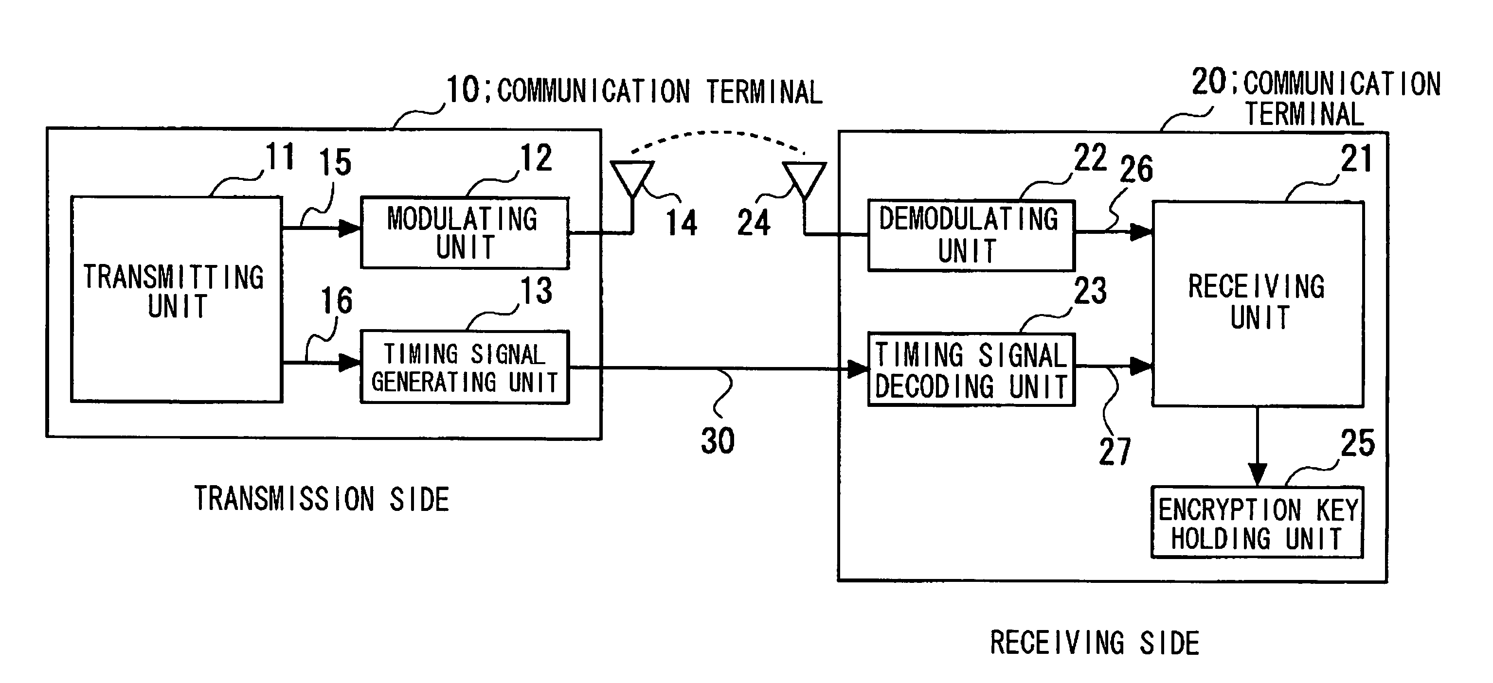
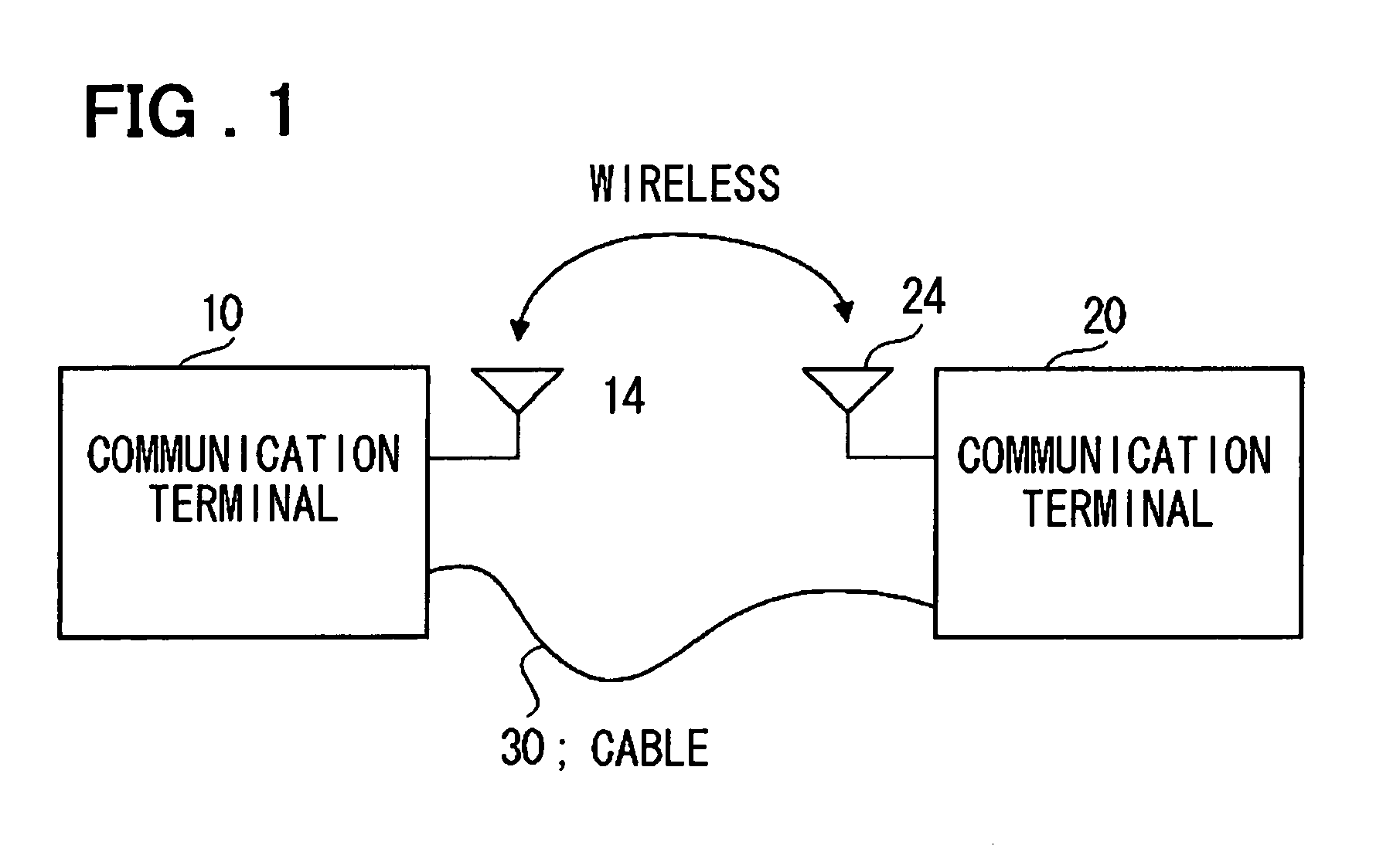
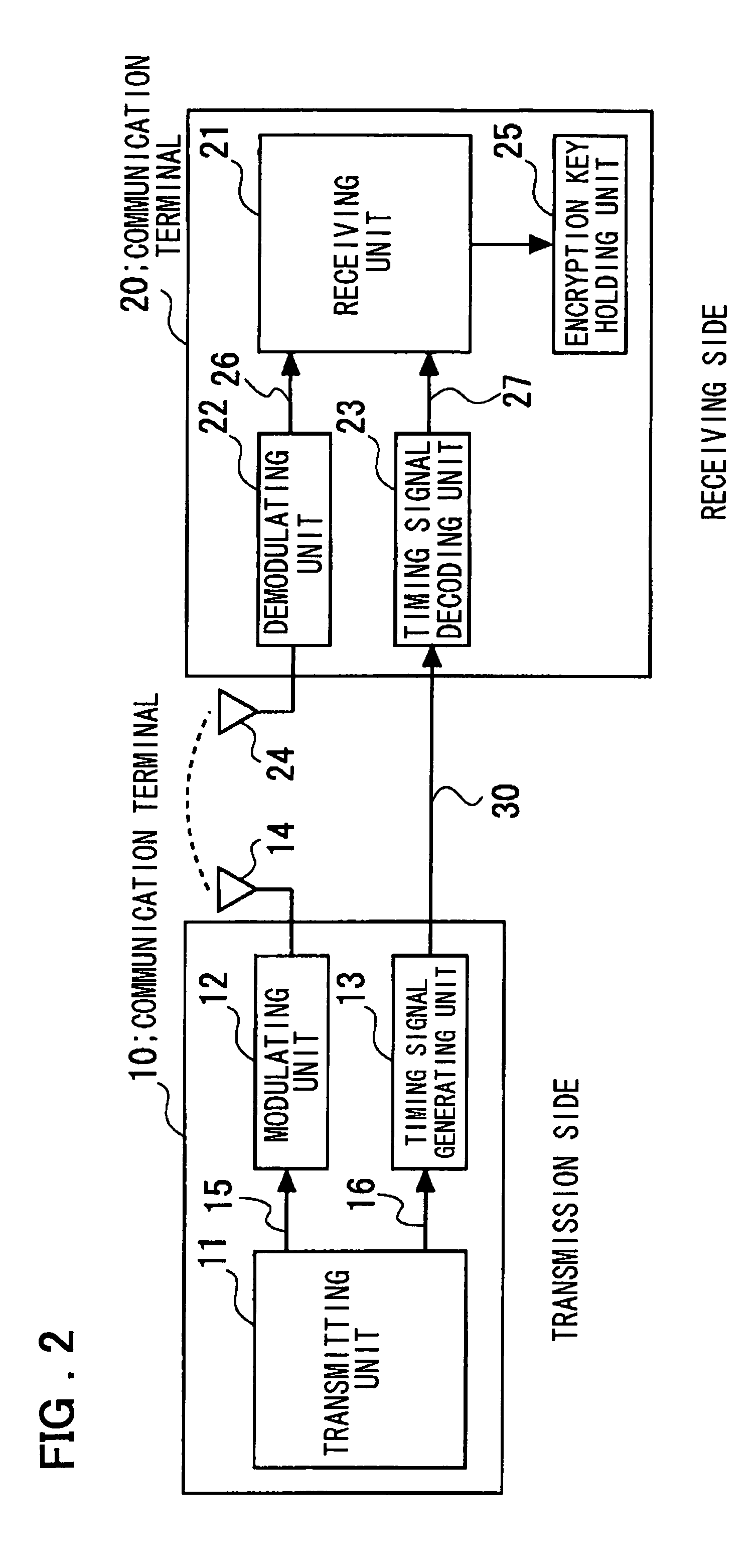
[0057]Preferred embodiments of the present invention will be described. FIG. 1 is a diagram showing a configuration of an embodiment of the present invention. Referring to FIG. 1, in a communication system according to the embodiment of the present invention, a communication terminal 10 and a communication terminal 20 which perform communication by wireless are connected by a cable 30. Then, while key information is delivered, the potential of the cable 30 is set to an active state. The potential of the cable 30 is set to an inactive state except while the key information is delivered. When the communication terminal (such as the communication terminal 10) for delivering a key transmits the key information by wireless communication, the communication terminal sets the potential of the cable 30 to an active state.

[0058]In the present embodiment, the communication terminal (such as the communication terminal 20) to which the key information is delivered by wireless communication regar...


PUM


Abstract

One and the other communication terminals for performing wireless communication are connected by a cable. The one communication terminal performs control so that an encryption key is transmitted from the one communication terminal to the other communication terminal by wireless during a period in which the potential of the cable is active. The other communication terminal stores the encryption key received from the one communication terminal within the period in which the potential of the cable is active, as a valid key, for use in subsequent encryption processing.

Description

FIELD OF THE INVENTION[0001]The present invention relates to a communication system. More specifically, the invention relates to a system, a device, and a method suitable for being applied to key distribution and the like between devices that perform wireless communication.BACKGROUND OF THE INVENTION[0002]In communication systems, in order to perform secure transmission and reception of information, various encryption methods have hitherto been employed. In a public key encryption system that uses two keys of a public key and a private key which become a pair, a property that information encrypted by one key (such as the public key) can be decoded only by the other key (private key) is used. The secure transmission of information to a communication party connected via a network is thereby enabled. When information is transmitted in accordance with the public key encryption system, the pair of the private key and the public key is generated by the receiver of the information, for exa...

Claims


Application Information

Patent Timeline
Patent Type & Authority Patents(United States)
IPC IPC(8): H04L9/00H04L9/08H04L9/30H04L29/06
CPCH04L63/061H04L9/0891H04W12/02H04L2209/80H04W12/03H04L9/30H04L9/32
Inventor MANABE, MASAO
Owner RENESAS ELECTRONICS CORP
Learn More